No questions about that. I'd be just curious to see what happen... what changes and how (if anything). 😊
D
Deleted member 148505
Hmm, this could be a topping LA90 alternative, reduce the gain as much as possible (like 2x or 6db) then create a low thd+n preamp/gain stage.I would say that one can play with this configuration, but maybe it would be useful to declare what kind of result should be achieved..
For comparison, here it is a not-so recent test of an experimental configuration of the original topology, a bit modified compensation, a bit modified gain and a different opamp in input (ADA4898) (-because it was actually on the board..)
Halving the gain brought the strongest contribution, decrease in THD.
(applied power in the test was: 8,5Vrms output on 5ohm >> 14,5W)

Thank you all for your answers and little discussion.
I've read that whole document and especially your quoted passage. That's why I asked. 🙂
I vaguely agree with point 1. With the exception of C10 (which isn't used anymore if I'm not mistaken), there's no apparent difference in compensation between a double inverting or double non-inverting scheme.
I don't understand point 2. The common mode voltage on the driving opamp is the same in either configuration (as mentioned by alexcp). I was curious if something else could be meant by Mauro, which could only be understood by looking at each opamp internals.
I don't understand point 3 in terms of the difference between inverting/non-inverting current pump. Maybe a language barrier.
Is the common mode rejection of the LM3886 its limiting distortion mechanism? The current pump is a differential amplifier. Running it purely inverting halves the common mode voltage compared to the purely non-inverting configuration. I take that 3dB if that's a limiting factor. Having a larger input than feedback resistor as in the my_ref makes it overall worse, though.
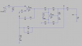
I like the idea of trying a current pump instead of the classic output buffer configurations. I guess there's nothing wrong running a configuration as attached? (I don't have a running LM3886 model in LTSpice yet, so bear with me. I only want to understand the overall topology at the moment)
Since this equals the classic composite amplifier configuration virtually any opamp could be used, I suppose. And eliminates any vagueness when compensating an opamp with its inputs swapped. Even though I find that insightful especially with the additional 1k input resistor as recently proposed by Joseph K and being discussed in the FE building thread.
@Joseph K1. The sequence of 2 inverting active stages allows you to use various techniques of compensation, and in favor of global stability and to "align" some related phases.
2. The connection of the input signal on the (-In) allows you to make the most of the internal characteristics of OPAMPs, which they tend to be more linear in this one configuration. (This is not an absolute rule, and varies greatly from case to case)
3. The "floating" condition facilitates the front- end in the process of "tracking" the voltage non-linearities present on the output load."
I've read that whole document and especially your quoted passage. That's why I asked. 🙂
I vaguely agree with point 1. With the exception of C10 (which isn't used anymore if I'm not mistaken), there's no apparent difference in compensation between a double inverting or double non-inverting scheme.
I don't understand point 2. The common mode voltage on the driving opamp is the same in either configuration (as mentioned by alexcp). I was curious if something else could be meant by Mauro, which could only be understood by looking at each opamp internals.
I don't understand point 3 in terms of the difference between inverting/non-inverting current pump. Maybe a language barrier.
Is the common mode rejection of the LM3886 its limiting distortion mechanism? The current pump is a differential amplifier. Running it purely inverting halves the common mode voltage compared to the purely non-inverting configuration. I take that 3dB if that's a limiting factor. Having a larger input than feedback resistor as in the my_ref makes it overall worse, though.
I like the idea of trying a current pump instead of the classic output buffer configurations. I guess there's nothing wrong running a configuration as attached? (I don't have a running LM3886 model in LTSpice yet, so bear with me. I only want to understand the overall topology at the moment)
Since this equals the classic composite amplifier configuration virtually any opamp could be used, I suppose. And eliminates any vagueness when compensating an opamp with its inputs swapped. Even though I find that insightful especially with the additional 1k input resistor as recently proposed by Joseph K and being discussed in the FE building thread.
Attachments

Nyx,
I see You are thinking around.. 🙂
Yes, you can do obviously also in this 'classic' double non-inverting configuration. Also I had played in these days with some thought-tests. Both this double non-inverting configuration and the input-inverting config brought up before can be massaged into work.
With inverting input there are loads of unconveniences, the only trustable way to make it working correctly is with an extra input buffer stage. And even then, it still inverts.. and all that only for that slight advantage of using the input opamp totally common mode signal free, in place of using it with a small level common mode signal. For me not really worth it.
The double non-inverting config is OK, classic. Using both stages in a less efficient mode, but OK as we had seen it.
Still there is a point: in the Myref arrangement at the ' Pin -In' the local FB loop is handled, at the ' pin +In' the global FB loop. So the respective compensations are working on separated nodes. Add to this the separated function for the input RF filter, (my latest mod) - and it results in a system nicely managed in separated blocks.
In the 'classic' double noninverting config (your sketch) the global/local compensations are all working onto the -In Pin. (The same for the config with inverting opamp input..) And I have noticed in the sims this less favorable condition. (the modded Myref Config is more 'efficient').
Not a big problem, difference, it will obviously work, one notes the difference only in direct comparison.
All the best, George
I think it could be fast to re-wire my usual 'test mule' for this 'classic mode'.. though I'm afraid only after Easter
Thank you for being so open for discussion. I am considering the Fremen edition as a project, but I am somewhat reluctant to build something that I haven't fully thought through for myself.
Hmm, my crude opamp simulation seems to prefer the double noninverting config for HF phase response... until I add small series resistances to the feedback capacitors. (No undamped series capacitors with me.) There certainly is a benefit in isolating the local feedback from the global feedback. Be it by the my_ref configuration or by isolating the local from the global feedback point be several kilo ohms at the cost of error correcting feedback. At least loopgain and transfer function look prettier that way, but who knows if that is audible.
By the way if a larger C33 than a few pF is used the isolating resistor from the input low pass should be increased as well it seems. That comes with a noise penalty, though.
I have a half working LM3886 model in LTspice now, but will have to check if its reliable.
Total noise is dominated by input and feedback resistors, yes? Not much one can do about it?
Yes, drawn on paper it looks so nice. Both for the input stage and the current pump. For the input stage as you described it and for the current pump it looks as if the input signal is handled by the negative feedback branch and the output signal by the positive branch. But I'm not sure if it is only the brain which forces you to think this way, because it is drawn that way, or if there's an electrical point to it. At least global phase response looks slightly different.Still there is a point: in the Myref arrangement at the ' Pin -In' the local FB loop is handled, at the ' pin +In' the global FB loop. So the respective compensations are working on separated nodes. Add to this the separated function for the input RF filter, (my latest mod) - and it results in a system nicely managed in separated blocks.
Hmm, my crude opamp simulation seems to prefer the double noninverting config for HF phase response... until I add small series resistances to the feedback capacitors. (No undamped series capacitors with me.) There certainly is a benefit in isolating the local feedback from the global feedback. Be it by the my_ref configuration or by isolating the local from the global feedback point be several kilo ohms at the cost of error correcting feedback. At least loopgain and transfer function look prettier that way, but who knows if that is audible.
By the way if a larger C33 than a few pF is used the isolating resistor from the input low pass should be increased as well it seems. That comes with a noise penalty, though.
I have a half working LM3886 model in LTspice now, but will have to check if its reliable.
Total noise is dominated by input and feedback resistors, yes? Not much one can do about it?
I concur in the major points.
Yes, total noise is dominated by the feedback & input resistances.
Feedback is dominated by the smallest value: (the equivalent is like if they were in parallel) - so some hundred ohm - depends on the gain setting.
But the input series resistances are a direct contribution. Here a FET input stage helps, because of the greatly reduced input current noise.
The extra contribution of that Rseries is it's thermal noise, that resistance is increased from 3,3k to 4,3k - - that is, from 7,3nV/sqrtHz to 8,3nV/sqrtHz.
In 20kHz bandwidth that is equivalent of : from 1uVrms to 1,2uVrms..
But this is only the resistor contribution, the rest is the opamp en (and negligible in), so the total is slightly more, the 1kohm extra effect is slightly less.
Anyway at this point yes, in this circuit the input series resistance will be the strongest contributor, in case of the lowest noise FET input opamps.
To decrease this effect while maintaining the RF filtering function either LC filtering would be needed (Brrr) or playing with the filter configuration, increasing C decreasing Rs.
But.. Why,, I am not a big fan of this 'noise fetishism'.... In my setup I hear total, dead silence emanating from the speakers. (4ohm, sensitivity cca 89dB..)
OPA828, FET input, low noise, and 4,3kohm input series resistance total..
Well it’s been running very stable for me. I do have couple of spare pcb for the RevA version.@aditya how has the response been for your amplifier? How did you manage to get the pcbs? We're they ordered or bought?
It'll be great if we could connect through DM
One head’s up you need precision 0.1% tolerance resistors for certain part of the circuit. Rest can be standard 1% resistors.
There is someone who said in this thread that normal 1% could be used for 0.1% but that is not the case and we need to follow the design as is.
Just as I was wondering, revA must've been custom locally manufactured ones, schematics taken from forum right?
Files are there in this thread buried some where you can get the pcb done your self also.Just as I was wondering, revA must've been custom locally manufactured ones, right?
Files are there in this thread buried some where you can get the pcb done your self also.
I will be grateful if the files can be shared. Please check pm
Sorry it’s tooo many post, you could find it by searching it.I will be grateful if the files can be shared. Please check pm
Thanks for trying my friend, however i found it from archives of the internet...
Posting here for the help of people in future!
Gerber files of MyrefA original stereo myref board by legendary mauro penasa.
I have also sent you pm, @aditya wanted to know how to get revA pcb and the parts to build it...
Posting here for the help of people in future!
Gerber files of MyrefA original stereo myref board by legendary mauro penasa.
I have also sent you pm, @aditya wanted to know how to get revA pcb and the parts to build it...
Attachments
any local Mumbai source?you need precision 0.1% tolerance resistors
- Home
- Amplifiers
- Chip Amps
- My "audiophile" LM3886 approach