Energy saving projects are good since cost of energy is going up in the forseeable future. Choose your projects well since the bi toroid and Tutur projects you mentioned are bottomless money pits.So I also already have all the stuff required for initial experiments re "energy saving" projects.
You need to separate the wheat from the chaff, the difference between incredibly good and too good to be true is sometime not that obvious. As a rule of thumb forget anything advertised as more than 100% efficient or overunity.
Last edited:
I already got a pack of solar cells able to generate ~1KW in full sun, plus ~10 KWh in LiFePO4 batteries and balancing units. Putting that to work the way I need it is very labor-intensive but in case of impending long emergency it gets priority.
For (also abandoned) PP tube projects I already had the required transformers for a few of the "flux" experiments - zero investment required. Belief in "overunity" I never had, only the idea that not all forces of nature are known. The difference between closed and open thermodynamic systems was obliged study material, long ago.
For (also abandoned) PP tube projects I already had the required transformers for a few of the "flux" experiments - zero investment required. Belief in "overunity" I never had, only the idea that not all forces of nature are known. The difference between closed and open thermodynamic systems was obliged study material, long ago.
RE bi-toroid transformer : https://www.slideshare.net/PDiCEOTh...black-box-system-efficiency-report-1-92418163 The data is interesting but I don't buy their description of over 100% power. Even the power factor stuff is murky at best. The real number seem to be 300W in, 15W out and no change no load to full load. Not really interesting.
I had to deal with this stuff- tech in search of a market and fuzzy rehash of old tech as the one responsible for pushing back on bad investments in tech at a major CE company. The sales BS just never ends.
I had to deal with this stuff- tech in search of a market and fuzzy rehash of old tech as the one responsible for pushing back on bad investments in tech at a major CE company. The sales BS just never ends.
The dissertation I posted
---
A project dissertation submitted to the
Electrical and Electronic Engineering Program
Universiti Teknologi PETRONAS
In partial fulfillment of the requirement for the
BACHELOR OF ENGINEERING (Hons)
(ELECTRICAL AND ELECTRONIC)
---
even provides a sim plus measurements for comparison. No mention where the "extra" energy comes from - only a statement "efficiency over 100%". However the amount of energy involved in all those transformer setups is very low (~10% of what "the iron" can deliver in traditional setup). AFAIK the project was done correctly. Power factor wasn't neglected either. I considered the results weird enough for some experiments (having everything needed for them, except maybe time).
---
A project dissertation submitted to the
Electrical and Electronic Engineering Program
Universiti Teknologi PETRONAS
In partial fulfillment of the requirement for the
BACHELOR OF ENGINEERING (Hons)
(ELECTRICAL AND ELECTRONIC)
---
even provides a sim plus measurements for comparison. No mention where the "extra" energy comes from - only a statement "efficiency over 100%". However the amount of energy involved in all those transformer setups is very low (~10% of what "the iron" can deliver in traditional setup). AFAIK the project was done correctly. Power factor wasn't neglected either. I considered the results weird enough for some experiments (having everything needed for them, except maybe time).
Be prepared to spend years on it since Thane himself is still working on it (at least 7 years already) and no product to show nor any follow up from UT Petronas.having everything needed for them, except maybe time
Indeed, after showing the effect there's no follow-up anywhere. A cost-benefit calculation makes quite clear that the only possible benefit (yet) regards very low power levels related to battery charging. But even that might have been made obsolete with the announcement of :
New Battery Can Self-Charge Without Losing Energy
https://scitechdaily.com/new-battery-can-self-charge-without-losing-energy/I'm still waiting for the car that refuels itself by letting the engine turning backwards.
Energy can't get lost, so the sum always remains 100%.
Energy can be transferred from one state into another state and back, but when some energy is consumed externally on the way in the conversion process, that energy will be no longer available for the reversal process itself.
That's why a perpetuum mobile can't be realized, because there is always some energy leaking away as heat, friction or whatever form and sooner or later all energy will be consumed by this leaking.
Hans

Correct enough for now, at least around here (the sol system). 🙂Energy can't get lost, so the sum always remains 100%.
The universe used to be considered an isolated closed system before dark energy hypothesis. Now nothing is certain anymore about conservation of energy at the macro universe level.
Last edited:
In continuation of the post:
https://www.diyaudio.com/community/...nterview-negative-feedback.94676/post-7252358
for those who do not understand:
high-speed distortion is nothing more than a loss of information. Moreover, the level of losses depends little on the amplitude of the signal.
With a large signal amplitude, the losses can reach 1% or more, and with small signal amplitudes (say, the higher harmonics of musical instruments), the losses can reach much greater values!
For those who want to understand the ongoing processes, here is the modified material
best regards
Petr
Attachments

Last edited:
True, so the question is "where did the energy for the big bang come from?"I'm still waiting for the car that refuels itself by letting the engine turning backwards.
Energy can't get lost, so the sum always remains 100%.
Energy can be transferred from one state into another state and back, but when some energy is consumed externally on the way in the conversion process, that energy will be no longer available for the reversal process itself.
That's why a perpetuum mobile can't be realized, because there is always some energy leaking away as heat, friction or whatever form and sooner or later all energy will be consumed by this leaking.
Hans
Answers that can be applied on lab level (for verification) will be much appreciated.
For your understanding, the so called speed distortion is a non existing distortion caused by a GD that is not flat for the whole spectrum of the testsignal to demonstrate this speed distortion.for those who do not understand:
high-speed distortion is nothing more than a loss of information. Moreover, the level of losses depends little on the amplitude of the signal.
I proposed you some time ago to get this proven with your testsinal on simple distortion free first order R-C filters with a -3dB point at resp 50Khz, 150Khz and 450Khz.
And yes, the higher the BW the less ultrasonic info from your testsignal will be lost, but this has nothing to do with distortion, it’s just attenuation with 6dB/oct.
Let’s wait and see if you accept the challenge for once.
Hans
... said the man who thinks he can design amps without even understanding simple RC filters. Hilarious!
Jan
Jan
Petr, as uC has quite a few ideal models, why not use them for peak-peak distortion (which is "what you hear")?
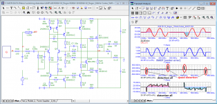
X14 = amp under measurement (10X).
X2,5 = absolute value, X7 = divider, X8 =multiplier.
So the inputs of X9 are the input voltage (Vin) to the amp under test and its output with exactly the same value as V(in). V10 is the peak-peak distortion (in the example caused by the diodes).

X14 = amp under measurement (10X).
X2,5 = absolute value, X7 = divider, X8 =multiplier.
So the inputs of X9 are the input voltage (Vin) to the amp under test and its output with exactly the same value as V(in). V10 is the peak-peak distortion (in the example caused by the diodes).
I agree with this. If the input signal at the input node of the diff pair is at a timepoint x, the signal needs to travel to the feedback node before any error can be corrected.The output signal turns out to be delayed in time (strictly speaking, this is not the same signal that is currently acting at the input). It is no longer clear what we subtract and from what. This difference (error signal) is unpredictable, and in this case the amplifier frantically tries to follow the input action that is difficult for it, it is on the verge of stability. The shorter the delay time of the signal (read - the greater the speed, the greater the SR), the more benefit and less harm from NFB.
So the diff pair will compare the input signal at timepoint [x + propagation delay] with the output signal at time point [x]
The problem becomes more significant with higer frequency of the input signal as the relative time error increases.
The differential pair compares apples with oranges.
What I do not agree with are the hf transients of musical instruments, a 192 kHz ADC has a bandwith of 96 kHz, a microphone maybe 40 kHz, CD audio 22 kHz very high frequencies are lowpass filtered and will never reach the amplifier.
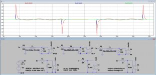
Since Petr evaded the confrontation, I made the sims with 3 distortion free first order R-C filters, their -3dB at resp 50Khz, 150Khz and 450Khz followed by a 26dB gain cell, in this way representing 3 main amps.
In the first image at the left you see Frequency responses and Group Delay, their values written in the plot.
At the right you see the output signals when driven with the same input signal as Petr is using.
In the second image you see the output signals minus the input signal matched in delay and amplitude.
Exactly what was to be expected, the higher the Amp's BW, the smaller the anomalies at start and stop, Petr's so called "speed errors" .
However be aware that all three Amps are free of THD and IMD distortion and that those glitches do not indicate any amplifier distortion.
It's just because their GD's are not flat over the whole input signal's BW , so it's a complete non issue.
Hans
Attachments

Hans, how about this. Because of the limited amp bandwidth, the higher frequency components cause a higher error amplitude at the differential input pair.
I agree with you that this is not distortion. But can you say, that at these instants the loop gain is lower (as shown by the higher error amplitude) so the distortion reduction ratio of the amp is smaller (the A(ol) is smaller in the A(ol)/(1-beta*A(ol)) classic equation).
That would mean that the existing distortion of the amp is reduced a bit less at those transients than during the steady state periods.
This is of course nothing new - distortion reduction depends on the loop gain that is available.
But it does not generate any (new) distortion. An ideal, distortion free amp remains distortion free also at those transients.
Jan
As to the erroneous ideas of feedback 'going round and round' still turning up, despite the efforts of many smarter than me.
Look at the two inputs of the diff pair. One signal is the input, the other comes from the feedback network. Normally the second signal is phase shifted and delayed by the transit time - those are two different things. The phase shift is for audio frequencies much larger than the transit time which can be ignored for now. But there is always a continuous signal at the feedback input to the diff pair - it is not like the diff pair gets an input and then has to wait for the feedback signal!
So what does the diff pair do when presented with two signals? It outputs an amplifed difference between the two. If the feedback signal is a bit smaller than the input, the diff output is higher then when they would be equal. And vice versa. (Assuming correct phase for now). But the feedback is still operating normally, and corrects the nonlinearities.
Now, as frequency rises, the error (difference between input and feedback signal) increases and the non-linearity is less corrected, but during all these conditions the feedback works as it should - but has less correcting power because the loop gain drops and the error rises.
Of course, at some point the freq gets so high that the feedback signal gets towards opposite phase to the input signal, the output of the diff pair increases where it should decrease (and v v), and the system becomes unstable. But - and this is important - it only becomes unstable because the feedback continues to work as it should! The physics are what they are.
Jan
- Home
- Amplifiers
- Solid State
- Musings on amp design... a thread split