https://www.diyaudio.com/community/threads/sound-quality-vs-measurements.200865/post-2847066
tvrgeek
«In this specific case, it does not require exotic or expensive design as a mere Rotel 840 or 951 passes her (note. his wife) subjective yes/no test, where a lot of others costing quite a bit more do not.»
https://www.diyaudio.com/community/threads/sound-quality-vs-measurements.200865/post-2840594
ThorstenL
«As such propagation delay clearly exists and is real, I think calling it an "audiophile myth" is rather disingenuous.
IF this propagation matters for the subjective sound quality of audio-circuits is a matter that may be debated, as the propagation delay is just another way of expressing other factors that can have an impact (but are also heavily disputed) one may suggest that low "propagation delay" may be used as an indicator of quality...»
The propagation delay time is at the heart of David Hafler's SWDT test. In fact, his own designs, including the XL-280, also fail this test.
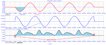
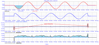
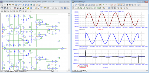
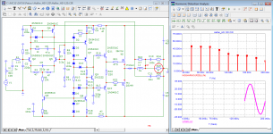
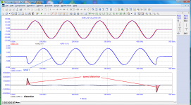
Let's try to figure out why relatively simple amplifiers like Rotel pass the listening test, while other amplifiers more complex and expensive do not. One of the possible reasons was suggested by Trostenl. Measurement of distortions by the compensation method sheds light on the nature of distortions. As tests show, it is in the first period that so-called high-speed distortions occur, which can exceed the levels of spectral components by tens and hundreds of times. It was the nature of these distortions that Graham Maynard tried to draw attention to with his FCD, but apart from ridicule from the “guru”, he did not receive anything in return. As an example, I give tests of two amplifiers for comparison.
I hope that everyone will draw their own conclusions.
tvrgeek
«In this specific case, it does not require exotic or expensive design as a mere Rotel 840 or 951 passes her (note. his wife) subjective yes/no test, where a lot of others costing quite a bit more do not.»
https://www.diyaudio.com/community/threads/sound-quality-vs-measurements.200865/post-2840594
ThorstenL
«As such propagation delay clearly exists and is real, I think calling it an "audiophile myth" is rather disingenuous.
IF this propagation matters for the subjective sound quality of audio-circuits is a matter that may be debated, as the propagation delay is just another way of expressing other factors that can have an impact (but are also heavily disputed) one may suggest that low "propagation delay" may be used as an indicator of quality...»
The propagation delay time is at the heart of David Hafler's SWDT test. In fact, his own designs, including the XL-280, also fail this test.
Let's try to figure out why relatively simple amplifiers like Rotel pass the listening test, while other amplifiers more complex and expensive do not. One of the possible reasons was suggested by Trostenl. Measurement of distortions by the compensation method sheds light on the nature of distortions. As tests show, it is in the first period that so-called high-speed distortions occur, which can exceed the levels of spectral components by tens and hundreds of times. It was the nature of these distortions that Graham Maynard tried to draw attention to with his FCD, but apart from ridicule from the “guru”, he did not receive anything in return. As an example, I give tests of two amplifiers for comparison.
I hope that everyone will draw their own conclusions.
Attachments
-
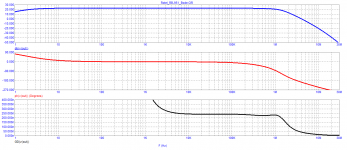 01_Rotel_RB-951_Bode.png9.1 KB · Views: 143
 -
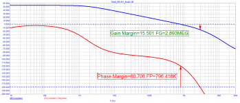 02_Rotel_RB-951_Loop-Gain.png12 KB · Views: 186
 -
 03_Rotel_RB-951_20kHz-spectr.png33.6 KB · Views: 180
 -
 04_Rotel_RB-951_10kHz(+)_SWDT.png17.1 KB · Views: 174
 -
 05_Rotel_RB-951_10kHz(-)_SWDT.png16.9 KB · Views: 139
 -
 06_Rotel_RB-951_X-over.png15.9 KB · Views: 163
 -
 01_Hafler_HD-220_Bode.png35.8 KB · Views: 151
 -
 02_Hafler_HD-220_Loop-Gain.png12.1 KB · Views: 172
 -
 03_Hafler_HD-220_20kHz-spectr.png34.5 KB · Views: 151
 -
 05_Hafler_HD-220_10kHz(-)-SWDT.png33.8 KB · Views: 156
 -
 06_Hafler_HD-220_X-over.png18.1 KB · Views: 136
Here's an interesting experiment:
Copypaste the amp.
Feed the output of the first amp to the second one, with voltage divider.
Instead of measuring speed distortion between the source and the first amp, measure it across the second amp (substracting its delayed input from its output).
Copypaste the amp.
Feed the output of the first amp to the second one, with voltage divider.
Instead of measuring speed distortion between the source and the first amp, measure it across the second amp (substracting its delayed input from its output).
Okay, let's do as you suggest.Here's an interesting experiment:
Copypaste the amp.
Feed the output of the first amp to the second one, with voltage divider.
Instead of measuring speed distortion between the source and the first amp, measure it across the second amp (substracting its delayed input from its output).
Attachments
drink a bottle of rum, feel betterI'm going to get another rum, I have a headache
off: human hearing is insensitive to the second and third harmonics, but has an amazing sensitivity (up to 0.001%!!! - 100 dB) to high harmonics, starting from the fifth.
Last edited:
Incorrect, "harmful" work of NFB.
The output signal turns out to be delayed in time (strictly speaking, this is not the same signal that is currently acting at the input). It is no longer clear what we subtract and from what. This difference (error signal) is unpredictable, and in this case the amplifier frantically tries to follow the input action that is difficult for it, it is on the verge of stability. The shorter the delay time of the signal (read - the greater the speed, the greater the SR), the more benefit and less harm from NFB.
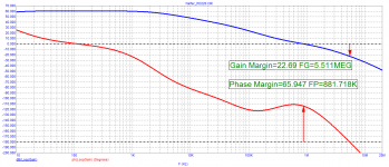
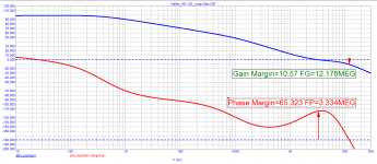
Matti Otala, back in his work in 1970, argued that “the slew rate must exceed the rate corresponding to the bandwidth of the amplified frequencies by a multiplier depending on the depth of the NFB and equal to at least 50, otherwise there will be impulse intermodulation distortion, T.I.M. Calculated according to this statement, the required slew rate for 20 kHz and 100 W into 8 ohms is 248.8 V/µs, and the bandwidth is 1 MHz! How many, even ultra-modern amplifiers, can boast of such a speed?! Very few, but they exist! The SR margin, combined with good linearity and a large gain margin, creates a very favorable forecast for the smallness of various signal distortions, including intermodulation distortions and high-order harmonic. The latter are most noticeable to our ears and are responsible for the "transistor" sound.
The output signal turns out to be delayed in time (strictly speaking, this is not the same signal that is currently acting at the input). It is no longer clear what we subtract and from what. This difference (error signal) is unpredictable, and in this case the amplifier frantically tries to follow the input action that is difficult for it, it is on the verge of stability. The shorter the delay time of the signal (read - the greater the speed, the greater the SR), the more benefit and less harm from NFB.
Matti Otala, back in his work in 1970, argued that “the slew rate must exceed the rate corresponding to the bandwidth of the amplified frequencies by a multiplier depending on the depth of the NFB and equal to at least 50, otherwise there will be impulse intermodulation distortion, T.I.M. Calculated according to this statement, the required slew rate for 20 kHz and 100 W into 8 ohms is 248.8 V/µs, and the bandwidth is 1 MHz! How many, even ultra-modern amplifiers, can boast of such a speed?! Very few, but they exist! The SR margin, combined with good linearity and a large gain margin, creates a very favorable forecast for the smallness of various signal distortions, including intermodulation distortions and high-order harmonic. The latter are most noticeable to our ears and are responsible for the "transistor" sound.
https://www.diyaudio.com/community/threads/sound-quality-vs-measurements.200865/post-2852781
tvrgeek
«Looking at 4k pulse my Rotel 840 driven system it "caught up" in 2 cycles. With my DH 120, it was closer to three.»
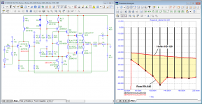
The situation with the DH 120 is even worse. It has a poor load capacity, a very long signal propagation delay, the spectrum of higher harmonics is very wide. Therefore, in this amplifier, the rule: "large loop gain = linearity" does not work.
tvrgeek
«Looking at 4k pulse my Rotel 840 driven system it "caught up" in 2 cycles. With my DH 120, it was closer to three.»
The situation with the DH 120 is even worse. It has a poor load capacity, a very long signal propagation delay, the spectrum of higher harmonics is very wide. Therefore, in this amplifier, the rule: "large loop gain = linearity" does not work.
Attachments


Interesting, it did the opposite of what I thought it would 😀Okay, let's do as you suggest.
Here's a bandlimited version of your test signal, as a microcap user source file. I wonder what that will do...
Attachments
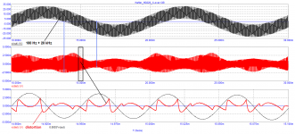
at a frequency of 100 kHz a whole bunch of distortions
for comparison, here is the operation of a single-stage amplifier at a frequency of 500 kHz at a load of 4 ohms
for comparison, here is the operation of a single-stage amplifier at a frequency of 500 kHz at a load of 4 ohms
Attachments
Last edited:
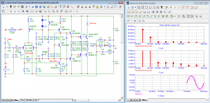
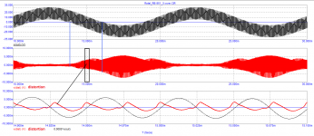
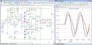
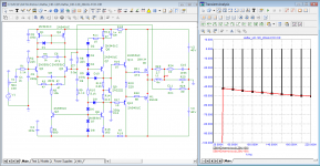
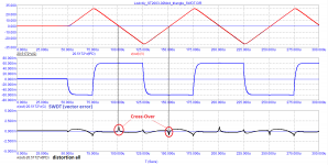
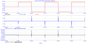
To meet the SWDT requirement, the attenuation of the differential signal in the high frequency region, according to David Hafler, must be at least 60 dB (1000 times). Thus, the difference signal should be no more than 30000 mV/1000 = 30 mV. In fact, we have 2 Volts. To measure the distortion products by the compensation method, we use the method of M.A. Sapozhkov (defended by her doctoral dissertation in 1954). To do this, we delay the signal of the first amplifier for the time tPD using the Zobel chain. The signal propagation delay in the HAFLER DH-120 amplifier is approximately 1 µs. How to do this and the test results are shown in the figures.
Attachments
https://www.diyaudio.com/community/threads/sound-quality-vs-measurements.200865/post-2856456
jan.didden
«… it will always be possible engineering wise to build a 'better' amp and I expect that other measurements may be required to proof that one amp is better than another, but I have no specific answer as to which measurements this might be.»
No ultra-modern laboratory and testing programs will help if you do not know what and how to measure in order to evaluate the quality of the amplifier.
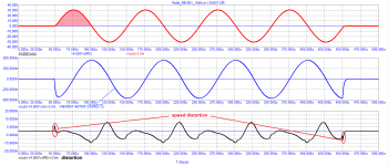
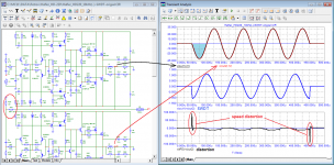
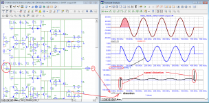
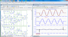
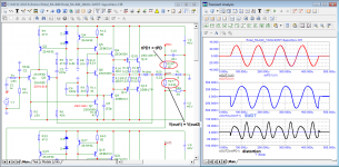
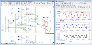
To evaluate why tvrgeek's wife rejected the DH-120 amplifier and did not reject the Rotel-840 amplifier (https://www.diyaudio.com/community/threads/sound-quality-vs-measurements.200865/post-2847066 ) just run simple tests and compare the distortions they introduce by the compensation method. It can be seen from the measurement results that the Rotel-840 amplifier has neither high-speed nor switching distortions. The distortion products are predominantly low-order harmonics to which hearing has low sensitivity. It is the high-speed distortions, which appear mainly in the first period, that determine the sound quality.
The test result of the Rotel-850 amplifier is shown in the same scale with the DH-120
jan.didden
«… it will always be possible engineering wise to build a 'better' amp and I expect that other measurements may be required to proof that one amp is better than another, but I have no specific answer as to which measurements this might be.»
No ultra-modern laboratory and testing programs will help if you do not know what and how to measure in order to evaluate the quality of the amplifier.
To evaluate why tvrgeek's wife rejected the DH-120 amplifier and did not reject the Rotel-840 amplifier (https://www.diyaudio.com/community/threads/sound-quality-vs-measurements.200865/post-2847066 ) just run simple tests and compare the distortions they introduce by the compensation method. It can be seen from the measurement results that the Rotel-840 amplifier has neither high-speed nor switching distortions. The distortion products are predominantly low-order harmonics to which hearing has low sensitivity. It is the high-speed distortions, which appear mainly in the first period, that determine the sound quality.
The test result of the Rotel-850 amplifier is shown in the same scale with the DH-120
Attachments
Wow - you are still at it?
What a stamina. Now, remind me -what are you after again? What is your end goal?
//
What a stamina. Now, remind me -what are you after again? What is your end goal?
//
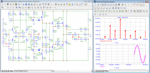
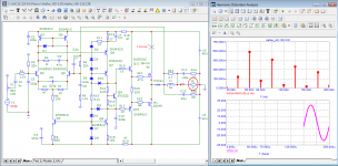
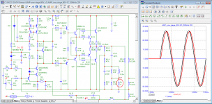
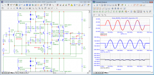
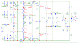
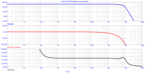
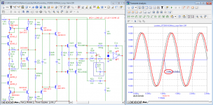
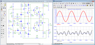
About 20 years ago, an amplifier based on a classical circuit with current feedback was published in the journal "Schemotekhnika".
I think that even today its parameters will be on top in comparison with many mediocre developments.
Here are the test results of his model
best regards
Petr
I think that even today its parameters will be on top in comparison with many mediocre developments.
Here are the test results of his model
best regards
Petr
Attachments
-
 01_Lozickiy_ST2003-02-Mod_SCH.png17.7 KB · Views: 186
 -
 02_Lozickiy_ST2003-02-Mod_Bode.png9.7 KB · Views: 181
 -
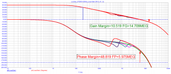 03_Lozickiy_ST2003-02-Mod_Loop-Gain.png14.6 KB · Views: 153
 -
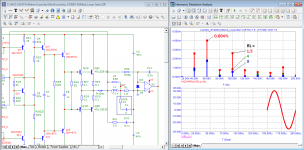 04_Lozickiy_ST2003-02-Mod_20kHz-spectr.png35.4 KB · Views: 145
 -
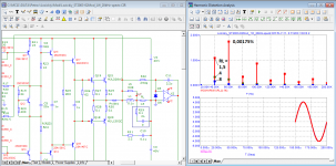 05_Lozickiy_ST2003-02-Mod_1W_20kHz-spectr.png35.2 KB · Views: 148
 -
 06_Lozickiy_ST2003-02-Mod_10kHz-SWDT.png18.5 KB · Views: 144
 -
 07_Lozickiy_ST2003-02-Mod_10kHz-triangle_SWDT.png16.1 KB · Views: 150
 -
 08_Lozickiy_ST2003-02-Mod_2kHz-square_SWDT.png11.1 KB · Views: 144
 -
 09_Lozickiy_ST2003-02-Mod_1MHz.png37.7 KB · Views: 145
 -
 10_Lozickiy_ST2003-02-Mod_333kHz.png38.3 KB · Views: 183
Ha, ha, how many years do you continue jumping to conclusions based on non validated tests while using misleading parameters that have no proven relation to audio perception.
You have made your point after repeating your thesis infinetely so lay back, we know your drill.
Hans
You have made your point after repeating your thesis infinetely so lay back, we know your drill.
Hans
stock up on popcorn and chew! as they say: he who laughs last laughs...Ha, ha, how many years do you continue jumping to conclusions based on non validated tests while using misleading parameters that have no proven relation to audio perception.
You have made your point after repeating your thesis infinetely so lay back, we know your drill.
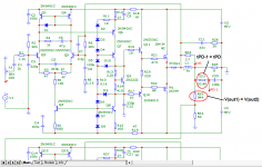
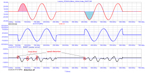
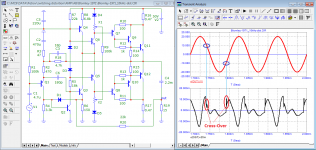
the music signal often crosses zero and switching distortion can have a significant effect. Douglas Self patented the transfer of switching distortion to one side by turning on the output of the CS on one power arm. Blomley solved this problem more elegantly back in 1971. He transferred switching distortion to + -10 V - an area where these distortions can appear very rarely.
best regards
Petr
best regards
Petr
Attachments
Well, that can only mean that you still hope to finally get the rewards for your persistency.stock up on popcorn and chew! as they say: he who laughs last laughs...
Let’s wait and see.
Hans

- Home
- Amplifiers
- Solid State
- Musings on amp design... a thread split