Jan, the Hafler test does not measure distortion, the Hafler test only measures vector errors, which are different concepts.
But using vector errors, you can calculate the signal propagation delay: I gave the formula above:
tPD = ~ = aT / 2piA
where
a - is the amplitude of the vector error;
T - is the period of the sinusoidal signal;
A - the amplitude of the signals at the outputs of the amplifiers;
pi - 3,14.
The calculation shows that the level of the vector error of -70 dB (3000 times) corresponds to a delay of 10 ns, which is not easy to implement in real amplifiers. A level of -50 dB (300 times) corresponds to a delay of 100 ns.
Hans, measure the Hafler vector error for a 10 kHz signal. Using the formula, you can calculate the delay time and compare it with the result measured in a different way earlier or, for example, using a double-beam oscilloscope between the input and output.
As for the measurement of distortions by the direct subtraction of signals, the Baksandall method (more precisely, the Sapozhkov method - defended by his doctoral dissertation in 1954) has one drawback: it does not take into account phase distortions, since it implies accurate phase matching before subtraction. In order to take into account all types of distortions (including phase distortions), the delay at the frequency of the test signal must be ideal (i.e., linear in a wide frequency band), and this is not so easy for a real amplifier to do. In the models, I use the ideal delay, it eliminates the possibility of skipping distortions caused by amplitude-phase conversion of signals.
The tuning of the models is painstaking; an accurate measurement of the transmission coefficient and signal transit time is required.
The delay time of the signal passage in the amplifier and the delay time in acoustics, to which the ear does not react, are completely different concepts! It's like claiming that an amplifier with 1ms or 2ms latency at 1kHz will sound great. Yes, such an amplifier will be completely inoperative.
The fact that speed distortions are associated with changes in both frequency and amplitude of the signal seems to be understood only by one Cortez:
Musings on amp design... a thread split.
Musings on amp design... a thread split.
Musings on amp design... a thread split.
Perhaps this is all that I wanted to convey, I hope that at least someone understood me ...
Hans:
“So to conclude, the GD theory affecting sound reproduction should be tested in a proper way, not with an oscilloscope but with humans.”
That's why I gave a link to Bob Carver's fight with "music lovers"
The Carver Challenge | Stereophile.com
You can artificially increase the signal delay time using correction (or just a small capacitor in parallel with the feedback resistor) in one of the channels 2 ... 3 times and compare the sound quality with each other.
Petr,
What is wrong with what I measured, results are correct to within 2%.
I have no intention to look at a “vector error” because vector errors do not exist, just frequency dependent phase shifts which is no error at all.
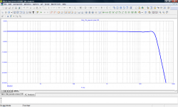
My amp’s measured phase shifts are translated in delay times in the shown graph.
No insane 10nsec but somewhere in the high 800nsec corresponding to a first order 250Khz filter.
That’s all there is, sorry lad.
Hans
What is wrong with what I measured, results are correct to within 2%.
I have no intention to look at a “vector error” because vector errors do not exist, just frequency dependent phase shifts which is no error at all.
My amp’s measured phase shifts are translated in delay times in the shown graph.
No insane 10nsec but somewhere in the high 800nsec corresponding to a first order 250Khz filter.
That’s all there is, sorry lad.
Hans
The Baxandall (with an 'x') test purpose is to show non-linear distortion by subtracting a non-distorted signal from a distorted signal. To do that you must correct for phase shift to get a null. It is a perfectly good method, except that it is not very sensitive as it is hard to get a deep null. Many here have made suggestions for better ways to measure non-linear distortion with high sensitivity.
Now, phase shift is another type of distortion, it is linear distortion, it does not create harmonics. There are methods to test that, but the Baxandall test is not designed to do it, and doesn't do it. Is that your problem? That a test NOT designed to show phase shift, does NOT show phase shift??
If you are so hung up on phase shift, then design a test to measure phase shift.
Jan
Last edited:
Now, phase shift is another type of distortion, it is linear distortion, it does not create harmonics.
petr's case is that it does
The fact that speed distortions are associated with changes in both frequency and amplitude of the signal seems to be understood only by one Cortez: ...
Not by accident. Cortez has been working on this topic for years and has serious achievements in this area. He understands what you're talking about. He is also well acquainted with the creator of Gauss Audio Opteron, Neuron and LZ Seven. These amplifiers are based on eliminating the "speed distortion" you just mentioned, using a topology never seen before. If you are interested, ask Cortez about the rest. Home | GAUSS AUDIO ELECTRONICS
Last edited:
I see just words when going to their website apart from a phase linearity<5 degrees from 100Hz to 10Khz.
My amp beats that with an ultra stable GD up to 150Khz, so where’s the phase distortion, I can’t see it, so why do some antique Hafler test.
A much better question to start with is, how much phase deviation from linear phase can be tolerated before becoming audible?
Test performed are showing that up to 3 Khz our hearing threshold is at a deviation of somewhere between 180 and 360 degrees and at higher frequencies as from 5Khz we can’t hear any phase distortion at all.
So let’s first set the borders of what is acceptable before jumping in the water with all sorts of extravagant tests.
Hans
to the question of the differences between sinusoidal signals (including multi-tone) and noise.
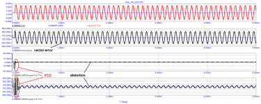
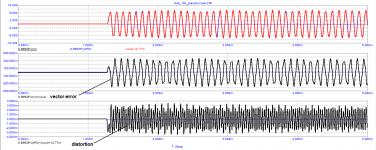
To verify the claim from patent SU90158, we will test a sinusoidal signal with a frequency of 10 kHz and a narrow-band pseudo-noise with a center frequency of 10 kHz.
As we can see on a clean signal, we see only the distortions of the first period that will not be detected by Audioprecision.
Without changing the settings, we switch the signal to pseudo noise.
At pseudo noise, the distortion is more than 30 times higher! (at least 30 dB)
Attachments
How do you generate this pseudo noise signal and what is the schematic being tested?
Last edited:
petr's case is that it does
Well if he feels phase shift causes harmonics that should be easy to prove, no? Even with a simulator.
Jan
to the question of the differences between sinusoidal signals (including multi-tone) and noise.
To verify the claim from patent SU90158, we will test a sinusoidal signal with a frequency of 10 kHz and a narrow-band pseudo-noise with a center frequency of 10 kHz.
As we can see on a clean signal, we see only the distortions of the first period that will not be detected by Audioprecision.
Without changing the settings, we switch the signal to pseudo noise.
At pseudo noise, the distortion is more than 30 times higher! (at least 30 dB)
The only thing this shows is that the GD is not flat around 10Khz.
What you have effectively made is an FM demodulator and what you call distortion is the recovered signal that modulated the original 10Khz signal.
So in your definition the sound from an FM radio is thus pure distortion 😀 😀 😀
Prove that I’m wrong by supplying the full details of the used circuit and the generated signal.
Hans
Well, this is in the style of petr_2009... Show unverifiable graphs and pretend that all the skeptics are defeated. A pseudo-noise that looks more like a sine curve than noise, a vector error graph that looks like a broken curve and raises suspicion that the calculation step is insufficient. In addition, it is necessary to look at the spectral composition of the results obtained.to the question of the differences between sinusoidal signals (including multi-tone) and noise.
To verify the claim from patent SU90158, we will test a sinusoidal signal with a frequency of 10 kHz and a narrow-band pseudo-noise with a center frequency of 10 kHz.
As we can see on a clean signal, we see only the distortions of the first period that will not be detected by Audioprecision.
Without changing the settings, we switch the signal to pseudo noise.
At pseudo noise, the distortion is more than 30 times higher! (at least 30 dB)
And I will also add that it would be nice to see the results of the same test with the same modeling settings for the second version of the correction from Bukvarev, which was so praised and set as an example. The experiment must be transparent and available for repetition, otherwise it can neither be confirmed nor refuted. I understand that the latter is painful and undesirable for you, but how else can you produce a scientific dispute?
Hi Fagos,
You are absolutely right.
I called it "graphical incontinence" instead of trying to understand that you cannot simply subtract (In & corrected Output) while using one tPD where the amp's group delay is not constant over the frequency range of the input signal.
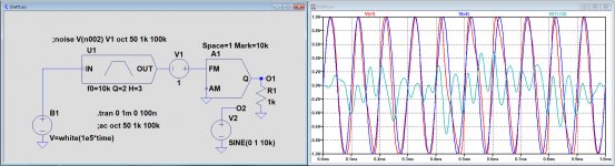
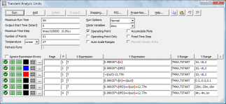
That's why made the example below.
I took a noise source B1, band-filtered the noise in U1 around 10Khz.
Then modulated a 10Khz signal with this noise in A1 and finally subtracted the output from A1 with a fixed 10Khz signal from V2.
So now I get (Input - Output corrected for tPD) at 10 Khz.
Result visible in teal as V(O1,O2), is this distortion, no of course not.
Hope that Petr will be able to understand this and stop producing "speed error" images.
Hans
.
You are absolutely right.
I called it "graphical incontinence" instead of trying to understand that you cannot simply subtract (In & corrected Output) while using one tPD where the amp's group delay is not constant over the frequency range of the input signal.
That's why made the example below.
I took a noise source B1, band-filtered the noise in U1 around 10Khz.
Then modulated a 10Khz signal with this noise in A1 and finally subtracted the output from A1 with a fixed 10Khz signal from V2.
So now I get (Input - Output corrected for tPD) at 10 Khz.
Result visible in teal as V(O1,O2), is this distortion, no of course not.
Hope that Petr will be able to understand this and stop producing "speed error" images.
Hans
.
Attachments
Part of the problem is the different languages spoken. Petr calls any difference between input and output 'distortion'. If you follow this, phase shift is 'distortion', amp gain is also 'distortion'.
This may however be a Google translate issue.
Jan
This may however be a Google translate issue.
Jan
petr_2009 claims that speed distortions occur when the amplitude or frequency of the signal changes, so he tries to pick up signals as much as possible similar to "real sound", as opposed to "stationary signals" like a sine or a mixture of two frequencies, hence the attempts to use noise, but what is the spectrum of the signal remains to be guessed. To my question, what is the significant difference between a real signal and a multiton, there was no answer. Let's check the difference with a correct comparison - with a signal without function breaks when the amplitude changes
Let's take the scheme with the correction from Nick, which was shown by petr_2009 above, and give a sine of 10 kHz with a decreasing amplitude. According to his statements, we should get vector distortions.

To set the signal, standard Microcap tools-in the Voltage Source, select the Sin mode, set the frequency to 10 kHz (just almost the upper end of the range) and DF=2000 (a dumping factor that will give us a damped amplitude without changing the frequency). In the resulting figure, after compensating for the delay, we get the usual linear distortions of the signal, the eye does not see any nonlinear effects, like those detected by petr_2009 (attach2)

Next, for comparison, we will submit the sine again and see if there are any differences (attach3).

Actually, no surprises.
But I will go further and see what the disconnection of C6 in the input filter on the attenuated sine (attach4) will give us. In this case, the delay is reduced to 44ps and you can ignore the compensation and just look at the difference signal input-output at the same scale of the graph and at a smaller scale.

To compare the results, I attach a graph (attach5) from petr_2009 from the Speed distortion.pdf file, previously posted somewhere on this forum.

Let's take the scheme with the correction from Nick, which was shown by petr_2009 above, and give a sine of 10 kHz with a decreasing amplitude. According to his statements, we should get vector distortions.
To set the signal, standard Microcap tools-in the Voltage Source, select the Sin mode, set the frequency to 10 kHz (just almost the upper end of the range) and DF=2000 (a dumping factor that will give us a damped amplitude without changing the frequency). In the resulting figure, after compensating for the delay, we get the usual linear distortions of the signal, the eye does not see any nonlinear effects, like those detected by petr_2009 (attach2)
Next, for comparison, we will submit the sine again and see if there are any differences (attach3).
Actually, no surprises.
But I will go further and see what the disconnection of C6 in the input filter on the attenuated sine (attach4) will give us. In this case, the delay is reduced to 44ps and you can ignore the compensation and just look at the difference signal input-output at the same scale of the graph and at a smaller scale.
To compare the results, I attach a graph (attach5) from petr_2009 from the Speed distortion.pdf file, previously posted somewhere on this forum.
Attachments
As for the comparative tests of pure tone and narrowband noise (1/3 octava), I pre-processed the signal from the output of the sound card with a 4th order Bessel filter. Both signals pass through this filter: a 10 kHz tone and a 10 kHz narrowband pseudo noise.
This is for your reference so that fagos does not load you with their speculations. The frequency response of the filter and the setting of the rendering are attached.
Well, now he is asking for the floor "head of the transport department" about the differences between noise signals and tones:
Musings on amp design... a thread split.
«I know the answer».
egra (Musings on amp design... a thread split.)
«Cortez has been working on this topic for years and has serious achievements in this area. He understands what you're talking about. He is also well acquainted with the creator of Gauss Audio Opteron, Neuron and LZ Seven. These amplifiers are based on eliminating the "speed distortion" you just mentioned, using a topology never seen before. If you are interested, ask Cortez about the rest. Home | GAUSS AUDIO ELECTRONICS »
thank you egra for your support and understanding!
Attachments
Last edited:
Peufeu, there are many DACs, both with and without negative feedback. With filters, not everything is clear. Some people prefer to use a filter at the input of the I / U converter, others at the output. Some even give up filters to avoid introducing phase distortion. Most often, a Bessel filter is used not higher than the 2nd order so that the phase shift at a frequency of 20 kHz is no more than 20 degrees.
In the test, I specifically applied a 4th order filter to better clean the signal from high-frequency products. In this case, the phase distortion of this filter does not affect the operation of the amplifier under test in any way, since the filter is located outside the amplifier.
In the test, I specifically applied a 4th order filter to better clean the signal from high-frequency products. In this case, the phase distortion of this filter does not affect the operation of the amplifier under test in any way, since the filter is located outside the amplifier.
- Home
- Amplifiers
- Solid State
- Musings on amp design... a thread split