OK, so you need some explanation: if you know that the audibility of group delay is above 1mS, even more at other frequencies, there's no way you can hear a micro-second or a nano-second group delay in your amp.
As I said about the Hafler test, it is very insensitive and inaccurate. Looking on a scope to determine distortion, really? Have you ever tried it?
Again, with a $ 100 sound card and free REW software you can measure much more sensitive and accurate.
Why are you so hung up on 50 year old tests while today we can do much, much better, much easier?
Edit: what do you expect to see from a clunky, hard to get right, insensitive Hafler test you can't get in a few minutes with some simple modern stuff?
I am really curious.
Jan
Last edited:
I already answered about Hafler test
You evidently have zero practical experiences with measurements of audio gear. Stick on your simulations and try to "reinvent wheel" in your paralel reality 🙄Why should I do it?? I tried it about 25 years ago..It will be lost time and no new information gained, this test is very inacurate.
Last edited:
Jan, BV - this is the opposite of your opinion.
Bob Cordell Interview: Negative Feedback
AKSA:
“I applaud Carver's technique, I think it's highly intuitive and nicely empirical.”
I received and continue to receive thanks for reminding me of this test method and explaining how to interpret the test results.
BV, if I understood correctly your amplifier, this test does not pass ...
Petr, instead of trying to find people on the internet that support a 50 year old test because they don't know any better, and you don't know any better, and taking it out of context, maybe, for a change, you can do some thinking for yourself?
It's a great technique for learning new stuff!
Jan
It's a great technique for learning new stuff!
Jan
Let me help you. Someone on the 'net says: 'its a great technique!' and you swallow that without thinking.
IF you would think, you would realize that balancing a main signal with a divided down signal with a potmeter or through multiple pots and/or variable caps is very hard, it will constantly drift, the potmeters will cause noise through the wiper contact that will prevent a very deep null. And then looking at the output on a scope you'll see 'something', no idea what harmonics they are, does it come from the amp or the measurement system? How to document it, and if you redo the test a few days later, it can be quite different due to factors mentioned. So, it may help with amps that have high distortion, higher than the system resolution, but not with high performance amps that you seem to favor.
Thinking a bit further, you realize that a soundcard + REW gives you consistent results from today or tomorrow, down to -120dB, showing all harmonic amplitudes and even phases, and separately the noise. Easily documented as PDF documents.
It really is a no-brainer. See, that's the sort of thinking I would expect from a smart guy like you, instead of random cutting and pasting parts of text found on the 'net. But hey, whatever floats your boat!
Jan
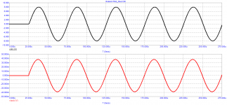
Petr, have you ever seen time recorg of multitone signal? This is according yuor opinion steady state signal?? Why should one fidlle with Hafler test, if we have now much better instruments to disclose all kinds of distortions???
You are sticking with thinking 20 years ago . And do not be worry, my amp perfom well, both in objective and subjective tests.
You are sticking with thinking 20 years ago . And do not be worry, my amp perfom well, both in objective and subjective tests.
Last edited:
my findings are as follows:
In the steady-state mode, there are no speed distortions, only vector distortions that are not measured by any tests other than simple signal subtraction, as is done in the Hafler test and is shown with examples in the book by Jiri Dostal. Velocity distortion occurs whenever both the frequency and amplitude of the signal change, which occurs continuously in real audio signals. And since the vector error is proportional to tPD, then the speed distortions are proportional to the vector distortions, and from them one can indirectly judge the quality of the amplifiers. The smaller the vector error, the less the speed distortions introduced by the amplifier, which are elusive by any other tests and which are responsible for the correct transmission of subtle nuances of the sound material.
In the steady-state mode, there are no speed distortions, only vector distortions that are not measured by any tests other than simple signal subtraction, as is done in the Hafler test and is shown with examples in the book by Jiri Dostal. Velocity distortion occurs whenever both the frequency and amplitude of the signal change, which occurs continuously in real audio signals. And since the vector error is proportional to tPD, then the speed distortions are proportional to the vector distortions, and from them one can indirectly judge the quality of the amplifiers. The smaller the vector error, the less the speed distortions introduced by the amplifier, which are elusive by any other tests and which are responsible for the correct transmission of subtle nuances of the sound material.
my findings are as follows:
In the steady-state mode, there are no speed distortions
Good that you finally have this insight. Congrats! So whats left as a problem for You is the start (dpearture from 0) of every song on a CD album.
my findings are as follows:
In the steady-state mode, only vector distortions
This is called group delay - it's the time it takes for a signal, of any frequency, to pass the amplifier - if you are not in a great hurry to listen to Beethovens 9:th, you have nothing to worry about.
Now, please do the world a favour - declare this topic to have been exhausted and stop the posting. Channel your resources towards soemting else. Nothing to see here folks 😉
//
I made a calculation of the density of the problem for you now once you realise that it is only the departure from a permanent zero state that is your concern. Of all the samples on a 80 min CD, the samples that will encounter your troubled situation is 0,000000047241119 of them.
And remember, it's only the leaving from a permanent state of zero that is a problem, not every 0 crossing because that is steady state.
//
And remember, it's only the leaving from a permanent state of zero that is a problem, not every 0 crossing because that is steady state.
//
Last edited:
From the history of the development of methods for measuring distortion in audio systems
Back in 1956, in the book "Measurements in film sound recording equipment" V. Rakovsky described in detail the main methods for measuring distortions and arranged them in the order of increasing correlation with sound quality.
1. method of one tone;
2. methods of two tones;
3. methods with a discrete spectrum (multi-tone);
4. methods using a continuous spectrum (one of them was patented by V. Wolf SU90158 in 1950 and demonstrated in 2009 at AES-126 by Professor A. Farina, the second more improved method was proposed by N. Bezladnov and described in the journal "Electrosvyaz" 1957 - 02. Unlike the previous method, the opposite is done: a narrow band of noise is cut out and fed to the amplifier, this band is cut out in the output signal, and the distortion products are measured in the remaining spectrum).
5. Methods with a working signal (the method was proposed by M. Sapozhkov and described in the "Acoustic Journal" 1956-03. In fact, this is a method that Baksandall proposed almost 20 years later and was widely used by I. Akulinichev).
Petr, I am trying to understand what you are saying.
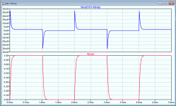
Can you tell me, what do you call the 'distortion' in the attached? It shows the difference between input and attenuated output with a low-passed square wave input.
Jan
Jan,
Don’t we know his answer after so many postings ?
In his terminology everything that differs from zero after subtracting in&out is distortion.
Vector distortion, speed distortion or whatever type.
Hans
He bases almost all his stuff on Jiri Dostal's opamp book. I have the 1981 edition, but not where I am now. So I have to wait a week or two before I can look it up.
The problem is that nobody seems to use these terms anymore so there's a lot of misunderstanding.
Jan
The problem is that nobody seems to use these terms anymore so there's a lot of misunderstanding.
Jan
Jan, I'll try to explain. I took out the vector error of the amplifiers, graphically representing the vectors of the input and output voltages, as well as the corresponding error vector between them. This is what we observe as residual peaks after exposure to a square wave in #615. However, petr_2009 does not understand in any way that if the circuit is excited by a signal with a limited rise rate, as we have after the simplest input filter, all these errors tend to zero.
In addition, it does not separate the concepts of linear distortion and nonlinear, mixing everything into one big salad. Hence his radical desire to expand the band as much as possible and get the highest rate of increase at the output, even at the cost of other parameters. Whether he understands it or not, but since GroupDelay is a derivative of the phase in frequency, this is exactly what he is doing, albeit indirectly. By giving an unlimited signal, he himself provokes a transient process in the circuit, and then pokes his finger at the results, calling this the reason for the differences in the sound of the amplifiers.
In addition, it does not separate the concepts of linear distortion and nonlinear, mixing everything into one big salad. Hence his radical desire to expand the band as much as possible and get the highest rate of increase at the output, even at the cost of other parameters. Whether he understands it or not, but since GroupDelay is a derivative of the phase in frequency, this is exactly what he is doing, albeit indirectly. By giving an unlimited signal, he himself provokes a transient process in the circuit, and then pokes his finger at the results, calling this the reason for the differences in the sound of the amplifiers.
Fagos thanks for the explanation.
I often look at the effective input voltage, the difference between +vi and -Vin, which basically is similar to the signal in # 615. Since the amp itself always runs open loop, this effective input signal will increase with frequency because of the decrease in open loop gain with frequency. That is the reason you see the 'error signal' at the square wave edges because these contain the highest frequency components where the open loop gain is lowest, so the effective input signal must be higher to maintain the output level. The feedback will make sure that it is maintained (almost).
But it is not harmonic distortion (although of course harmonic distortion does increase with decreasing loop gain).
I agree that you can't have a meaningful discussion if you don't make a difference between linear and non-linear distortion.
Jan
Last edited:
Graham Maynard repeatedly pointed out that the amplifier has two inputs:
- amplifier input;
- amplifier output - it is also the input for back EMF
Bob Cordell Interview: Negative Feedback
«Thus the output terminal of an amplifier becomes an input terminal for the closed amplifier
system, and delayed NFB control cannot prevent the generation of an error wrt normally amplified input before the NFB loop can establish output terminal control».
Graham was supported by John Curl:
Bob Cordell Interview: Negative Feedback
«Stay the course, Graham».
I have repeatedly noticed that the phase of the output resistance corresponds to the phase of the loop amplification, which in turn depends on the frequency of the first pole. At a low frequency of the first pole (below 100 Hz), the phase of the output impedance is 90 degrees in the entire sound band.
Cyril Hammer:
«The theoretical concept of negative feedback is very powerful, and the simplified mathematical equations describing this concept do hold true. But they are only valid if the design addresses the limitations of the concept. The time delay from input to output must be zero! Obviously in real life this is not possible. There are two ways to deal with this problem. Either you just do not apply any negative feedback at all to your design (while giving up the advantages of the concept) or you do speed it up to the level of a few nanoseconds of time delay from input to output»
Why doesn't an amplifier without feedback spoil the sound?
Take the Jeff Rowland model 7Mk2 amplifier for example. His Bode diagram shows that the signal propagation delay is over 800 ns. But why doesn't such a long delay lead to degradation of the sound? To do this, measure the output impedance at the upper frequency of the audio range.
The test shows that the output impedance coincides with the phase of the external stimulus. The amplifier reacts to the signal almost instantly and accurately, without transient processes. Since there is no general negative feedback, there is no second input to the amplifier. Hence, it is not surprising that although the amplifier does not have very low distortion (as amplifiers with deep GFB formally have), the sound quality is unattainable for most of the low-distortion amplifiers with an order of magnitude lower distortion.
A good lesson on the Haffler test came from Bob Carver:
The Carver Challenge | Stereophile.com
Offtopic: I have never met so many naive visitors anywhere.
Attachments

Last edited:
The test shows that the output impedance coincides with the phase of the external stimulus. The amplifier reacts to the signal almost instantly and accurately, without transient processes.
How linear is this output impedance?
Well, Cyril Hammer obviously didn't understand negative feedback. And he is not the only one. Many think that the phase shift around the loop somehow causes the feedback to not work, unless it is infinitely fast (which it isn't of course). He makes the classical error to confuse phase shift with delay.
At zero (or very low) frequency, the feedback is in phase with the input signal (because the output signal, where the feedback comes from is in phase with the input signal). That means that the effective input signal (difference between Vin and Vfeedback) is very, very small; it is Vout/Aol of course.
As frequency rises, amplifier gain drops and phase shift rises. That means that the difference between Vin and Vfeedback gets bigger and bigger - subtracting two signals that are not in phase leaves a difference that is not very small, it gets higher with frequency. The amplifier itself has not changed - (Vin - Vfeedback) is still Vout/Aol - but because Aol has dropped with frequency, (Vin - Vfeedback) has increased.
The feedback mechanism still works of course, how could it not? But it is less effective in reducing distortion at higher frequencies because the Aol is less (which of course is the reason why (Vin - Vfeedback) rises), so the loop gain Aol/Acl that can be used to reduce distortion is lower.
There is no mystery or unknowns in the above, it is basic to the concept since 1934 when Harold Black first documented it.
And your statement: "Hence, it is not surprising that although the amplifier does not have very low distortion (as amplifiers with deep GFB formally have), the sound quality is unattainable for most of the low-distortion amplifiers with an order of magnitude lower distortion." is simply wrong. This amp has more distortion and more non-linearities than a similar amp with feedback thus is much less 'perfect'.
Jan
Last edited:
@Petr: I am still amazed how you go for cut and paste from anywhere on the internet, without any reasoning and thinking, apparently hoping that somehow we will be impressed? I say again: try to think for yourself for a change!
Jan
Jan
I almost shed tears when Graham told me about the obvious things. Do you really think that no one knows? Perhaps it's time for you to finally stop being naive and start evaluating the differential input voltage. Then life will become easier and what is happening will become more meaningful.Graham Maynard repeatedly pointed out that the amplifier has two inputs:
- amplifier input;
- amplifier output - it is also the input for back EMF
I only have two questions.Why doesn't an amplifier without feedback spoil the sound?
Take the Jeff Rowland model 7Mk2 amplifier for example. His Bode diagram shows that the signal propagation delay is over 800 ns. But why doesn't such a long delay lead to degradation of the sound? To do this, measure the output impedance at the upper frequency of the audio range.
The test shows that the output impedance coincides with the phase of the external stimulus. The amplifier reacts to the signal almost instantly and accurately, without transient processes. Since there is no general negative feedback, there is no second input to the amplifier. Hence, it is not surprising that although the amplifier does not have very low distortion (as amplifiers with deep GFB formally have), the sound quality is unattainable for most of the low-distortion amplifiers with an order of magnitude lower distortion.
1) Have you actually heard the Jeff Rowland model 7Mk2 amplifier to claim that it does not spoil the sound?
2) How many deep feedback amplifiers have you heard and which ones to claim that the sound quality of the Jeff Rowland model 7Mk2 amplifier is not achievable for them?
- Home
- Amplifiers
- Solid State
- Musings on amp design... a thread split