The thing I find most hilarious is that Petr needs no audience.
It’s a sort of electronic incontinence that keeps him going and going, almost like a perpetuum mobile, absolutely unstoppable. 😀 😀
Hans
It’s a sort of electronic incontinence that keeps him going and going, almost like a perpetuum mobile, absolutely unstoppable. 😀 😀
Hans
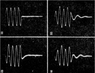
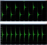
I am more and more amazed at how many people here are far from sound engineering. Pulse signals are widely used in audio frequency amplifier tests: from rectangular signals, triangular signals to bursts of sinusoidal signals. For example, bursts of sinusoidal signals are recorded on a magnetic tape to check the frequency response of the playback channel. The generator of a set of packets of signals from 300 ... 400 Hz to 18 ... 20 kHz is used to check the frequency response of the recording-playback channel of tape recorders.
Attachments

I am more and more amazed at how many people here are far from sound engineering. Pulse signals are widely used in audio frequency amplifier tests: from rectangular signals, triangular signals to bursts of sinusoidal signals. For example, bursts of sinusoidal signals are recorded on a magnetic tape to check the frequency response of the playback channel. The generator of a set of packets of signals from 300 ... 400 Hz to 18 ... 20 kHz is used to check the frequency response of the recording-playback channel of tape recorders.
I'm amazed how someone can be so blind to the reality. Worked on all types of reel to reel tape recorders (calibrating from reference tapes ) for 20 years and I never saw a signal like that. How would 6 cycles of 100hz show you anything on a VU meter? Like the rest of this thread you just make stuff up and run with it. Yes pulse signals can be used but you have to understand what they mean, you don't.
Last edited:
сbdb, where did you get the idea that these are signals with a frequency of 100 Hz. I clearly wrote that the lower frequency is used not lower than 300 Hz, and most often 400 Hz.
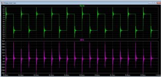
I take the first model I come across with a tPD of less than 100 ns and run exactly the same test. Compare and feel the difference.
I take the first model I come across with a tPD of less than 100 ns and run exactly the same test. Compare and feel the difference.
Attachments

So sorry 6 cycles of 400 hz is completely different and so much more useful than 6 cycles of 100 hz. Talk about not seeing the forest for the trees! Your tests, as everyone and there dog has pointed out to you are useless and mean nothing. I'm only hear for the amusement.
Or, for example, compare with the test result of this modification of the amplifier by Hiraga. I hope the comments are superfluous
Cbdb, if my tests mean nothing to you, just pass by and do not flood. Those for whom they mean something will find a lot of useful things for themselves.
Cbdb, if my tests mean nothing to you, just pass by and do not flood. Those for whom they mean something will find a lot of useful things for themselves.
Attachments
Last edited:
Otala came to the conclusion that the first pole of the amplifier should be above the audio range.
This concept was adopted by the legendary developer John Curl and adheres to it to this day.
His developments are recognized as one of the best in sound quality in the world.
In my opinion, the high first pole has the following advantages:
- the depth of the loop gain in the audio range is constant;
- the output impedance in the audio range is also constant and has a minimum phase shift (and therefore maximum speed) with respect to external influences (for example, to the back-EMF of a loudspeaker).
However, you can find statements of the opposite nature, such as: the frequency of the first pole does not mean anything, they say, the depth of the OOS decides everything.
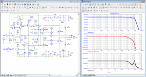
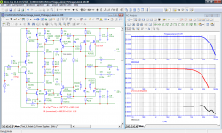
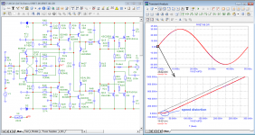
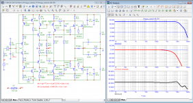
For comparison, let's take two models of amplifiers with current feedback (CFB) made on the same element base, with the same supply voltage + -40 V and with the same cascade operating modes: modification of the Hiraga amplifier and the PIRET-96 amplifier.
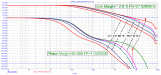
If we compare the Bode diagram, we can see that the amplifiers have the same parameters: a gain of 26 dB and approximately the same time Propagation Delay.
The frequency of the first pole of the PIRET-96 amplifier is slightly higher than 2 kHz, and the Hiraga amplifier is an order of magnitude higher.
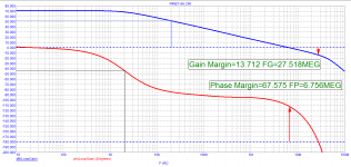
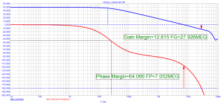
Phase and gain margins are approximately the same.
The loop gain in the sound band of the PIRET-96 amplifier is higher (up to a frequency of 2 kHz - by 20 dB).
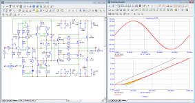
Despite approximately the same cascade modes and a higher loop gain at a frequency of 20 kHz, the PIRET-96 amplifier has a much higher level of distortion introduced by it.
This concept was adopted by the legendary developer John Curl and adheres to it to this day.
His developments are recognized as one of the best in sound quality in the world.
In my opinion, the high first pole has the following advantages:
- the depth of the loop gain in the audio range is constant;
- the output impedance in the audio range is also constant and has a minimum phase shift (and therefore maximum speed) with respect to external influences (for example, to the back-EMF of a loudspeaker).
However, you can find statements of the opposite nature, such as: the frequency of the first pole does not mean anything, they say, the depth of the OOS decides everything.
For comparison, let's take two models of amplifiers with current feedback (CFB) made on the same element base, with the same supply voltage + -40 V and with the same cascade operating modes: modification of the Hiraga amplifier and the PIRET-96 amplifier.
If we compare the Bode diagram, we can see that the amplifiers have the same parameters: a gain of 26 dB and approximately the same time Propagation Delay.
The frequency of the first pole of the PIRET-96 amplifier is slightly higher than 2 kHz, and the Hiraga amplifier is an order of magnitude higher.
Phase and gain margins are approximately the same.
The loop gain in the sound band of the PIRET-96 amplifier is higher (up to a frequency of 2 kHz - by 20 dB).
Despite approximately the same cascade modes and a higher loop gain at a frequency of 20 kHz, the PIRET-96 amplifier has a much higher level of distortion introduced by it.
Attachments
-
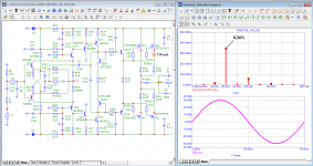 04_PIRET-96_20kHz-spectr.png92.6 KB · Views: 98
 -
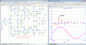 04_Hiraga-AB_Lateral_20kHz-spectr.png91.3 KB · Views: 108
 -
 03_PIRET-96_20kHz-FCD.png91.2 KB · Views: 100
 -
 03_Hiraga-AB_Lateral_20kHz-FCD.png95.6 KB · Views: 106
 -
 02_PIRET-96_Loop-Gain.png33.2 KB · Views: 97
 -
 02_Hiraga-AB_Lateral_Loop-Gain.png33 KB · Views: 103
 -
 01_PIRET-96_Bode.png89.8 KB · Views: 108
 -
 01_Hiraga-AB_Lateral_Bode.png85 KB · Views: 128
"Otala came to the conclusion that the first pole of the amplifier should be above the audio range. This concept was adopted by the legendary developer John Curl and adheres to it to this day."
Yes, it is easy to find people that agree and are both wrong. Cordell started to explain to you, it looked to me you Got It (you even thanked him) but you apparently immediately forgot the learned lesson.
How strange the world must look for you!
Jan
Yes, it is easy to find people that agree and are both wrong. Cordell started to explain to you, it looked to me you Got It (you even thanked him) but you apparently immediately forgot the learned lesson.
How strange the world must look for you!
Jan
If we compare the Bode diagram, we can see that the amplifiers have the same parameters: a gain of 26 dB and approximately the same time Propagation Delay.
The two amps are completely different. The Hiraga uses nested feedback, the Piret does not. I suggest you plot the open loop gain of the inner loop of the Hiraga.
I could have used infinite slew rate sq wave since petr_2009 includes infinite harmonic series in his test signal. The rise time is 100nS as he is touting extended bandwidth. It appears he is happy with distorted square waves.
My exchange with Bob Cordell on slew rates did not make a dent. Neither does John Curl suggesting a practical upper limit of 100V/uS. Slew rate in my world is at the load, not some marketing figure.
My exchange with Bob Cordell on slew rates did not make a dent. Neither does John Curl suggesting a practical upper limit of 100V/uS. Slew rate in my world is at the load, not some marketing figure.
Yes Jan, I thanked Cordell for the answer, for the work he did ... When I started reading the book by Douglas Self (it was published in Russian in 2009), at every step I had comments about the contradictions. I ended up putting it on the shelf as a useless manual. Although it can be used to make a workable amplifier, but nothing more. Much more practical information can be found in John Curl's advice, although he does not provide practical circuits or amplifier node circuits like Bob Cordell's book and which can be found in many real amplifier circuits since the 1960s.
Jan, Graham Maynard more than 15 years ago tried to open the eyes of you and many others to the first period distortion (FCD), but nobody understood anything. More than 15 years have passed, and you have not made any progress in understanding the essence.
As they say in Odessa "there are two big differences between distortions in steady state (what Audioprecision shows) and how the amplifier reacts to any deviation of the signal from the sinusoid (change in frequency, change in amplitude)"
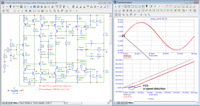
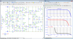
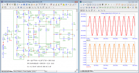
spladski, I have been working with microcap for over 15 years. With his help, a number of industrial amplifiers were improved and he never let me down. I also tested the resistance of the Hiraga modification to reactive load, here are the results
Jan, Graham Maynard more than 15 years ago tried to open the eyes of you and many others to the first period distortion (FCD), but nobody understood anything. More than 15 years have passed, and you have not made any progress in understanding the essence.
As they say in Odessa "there are two big differences between distortions in steady state (what Audioprecision shows) and how the amplifier reacts to any deviation of the signal from the sinusoid (change in frequency, change in amplitude)"
spladski, I have been working with microcap for over 15 years. With his help, a number of industrial amplifiers were improved and he never let me down. I also tested the resistance of the Hiraga modification to reactive load, here are the results
Attachments

In my opinion, prophetic words:
First cycle distortion - Graham, what is that?
millwood:
“I hold a lot of respect for Graham, as well as any member on this forum and I think if proven true, FCD can be a revolutionary step forward in our understanding of audio and human hearing.”
In fact, he gave the definitions of distortions. I got it much earlier, see the attached file. If you ask yourself the level of distortion, then it is easy to calculate using formulas 6.5 what parameters your amplifier should have in this case.
Spladski:
«It appears he is happy with distorted square waves.»
Look at the 1 kHz square-wave output from the CD player.
Attachments
Last edited:
Slew rate calculations - how much do I need?
john curl
Folks, I don't know if I can make better sense of everything that you are talking about, but slew rate is a LIMITING CONDITION that you don't want to approach. Do you need 500V/us? Couldn't hurt!
I absolutely agree with John Curl that today there is not a single book that could really teach the understanding of the correct design of audio amplifiers (with the exception of a number of articles by Hawksford).
Negative feedback theory is a powerful tool, but few people understand how to use it correctly to get results. Most of him use it as my neighbor hammering in nails with a saucepan.
Last edited:
- Home
- Amplifiers
- Solid State
- Musings on amp design... a thread split