BTW It's nice to be able several instances of uC on the same computer, but the limitation remains CPU speed. Running IMD for an audio amp and simultaneously running a feedback PLL would make both too slow for comfort.
LTSpice has some internal tweaks that allow for faster convergence and processing. They were essential for modelling switching supplies (of course). Microcap can be quite slow. These ultra low THD numbers relate to the accuracy and shortcuts in the models. Its all a fun numbers exercize but has very little relationship to the reality in the circuit board.
I find the simulations great for checking biases operating points frequency response etc. However not useful for optimizing distortion below .1%. You can find the seriously nonliner places in the circuit but the models are just not complete enough for PPM level analysis. That may be why you can get such absurdly great numbers.
I find the simulations great for checking biases operating points frequency response etc. However not useful for optimizing distortion below .1%. You can find the seriously nonliner places in the circuit but the models are just not complete enough for PPM level analysis. That may be why you can get such absurdly great numbers.
It is like you start metal work with primitive tools. You use them to make better tools, then you built a simple machine, with the machine you fabricate better tools to again built a even better machine. Finally you end up with tolerances of 1/000 mm.
It takes 10 years to sharpen a sword.
Chinese saying.
It takes 10 years to sharpen a sword.
Chinese saying.
Still possible to do normal work on the circuit in the second running program.Running IMD for an audio amp and simultaneously running a feedback PLL would make both too slow for comfort.
No. There are other reasons.These ultra low THD numbers relate to the accuracy and shortcuts in the models.
It takes 10 years to sharpen a sword.
Models indeed are (sometimes gross) simplifications of behavior. It's quite obvious to some that when the numbers are far better than the specs from producer(s), the outcome is likely to be too optimistic. One cautionary measure is to test the model itself in a sim, and compare with producer(s) spec. Sometimes the difference is quite hilarious.
Do you have a power amp schematic that gives you such low numbers below -200 dB?That may be why you can get such absurdly great numbers.
Let‘s say one ccs is better in a low thd circuit than another, which one would you choose?
The difference would not show up in a normal circuit.
The difference would not show up in a normal circuit.
I do not say my physical amp has or will have -240dB THD, not need to discuss such things, but imho the circuit that simulates better will also perform better in reality.
So I look for the best.
So I look for the best.
Last edited:
How can I get such fft graph in harmonic distortion analysis ?????
No idea what "normal work" means: for me it's RF (high dynamic range - low noise) antenna amps, feedback PLL (threshold far below that of standard RX), and KISS type audio amps with "below 60 dB" low order distortion. All together slow down the system to the extent that even browsing becomes rather slow.Still possible to do normal work on the circuit in the second running program.
Normal work means to make changes to the circuit, run a short transient analysis <— checked that, no problem.
Of course not run THD and IMD at the same time.
Of course not run THD and IMD at the same time.
I would also consider the effect of temperature (preventing runaway issues).Let‘s say one ccs is better in a low thd circuit than another, which one would you choose?
The difference would not show up in a normal circuit.
There is nothing wrong with simulations imho - as long as the underlying models represent reality accordingly. So I do share the opinion of 1audio. But with THD numbers in the region of 200dB you are far below realistic modelling - and it is impossible to prove that these numbers may become realistic at some point. Also the conclusion, that improving simulated THD from maybe -180 dB to -250dB improves your amp is nothing more than an assumption not backed up by evidence. Without a possibility of verification this whole debate is just a theoretical kind of sport without practical relevance.
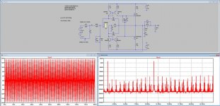
For no other reason then be able to compare LTSpice to Microsim, I simulated your circuit diagram, without knowing what Bias and what Mosfets you used.Yep, and the reason is to keep THDN at 100 mW "low enough". This because the opamp used is VERY noisy but one of the few, allowing this topology:
View attachment 1145426
The Mosfets I used needed a 4Volt Vgs for 250mA Bias, so I limited Vout to slightly under +/-20Volt peak to prevent clipping.
Plot that came out showed IMD somewhere at -120dB, which seems quite realistic for an opamp having a THD of of -104dB at +/-15V@1Khz.
So my impression is still that Microsim is very optimistic with distortion figures.
When you think the Mosfets that you used improve IMD, please give me de Spice models plus the bias current that you used.
Hans
Attachments
I‘m sure there are schematics of amplifiers around that perform as good as -200dB or better in simulation, I just was‘nt lucky enough to find one. Maybe you have a example ?But with THD numbers in the region of 200dB you are far below realistic modelling
That was more interesting than I expected: I don't use those mosfets in such application but instead, use the ECW20 series.For no other reason then be able to compare LTSpice to Microsim, I simulated your circuit diagram, without knowing what Bias and what Mosfets you used.
The Mosfets I used needed a 4Volt Vgs for 250mA Bias, so I limited Vout to slightly under +/-20Volt peak to prevent clipping.
Plot that came out showed IMD somewhere at -120dB, which seems quite realistic for an opamp having a THD of of -104dB at +/-15V@1Khz.
So my impression is still that Microsim is very optimistic with distortion figures.
When you think the Mosfets that you used improve IMD, please give me de Spice models plus the bias current that you used.
Hans
This is not my point. My point is that simulations with such ridicolous low THD numbers never can be verified in a physical test that makes them pretty useless imho.I‘m sure there are schematics of amplifiers around that perform as good as -200dB or better in simulation, I just was‘nt lucky enough to find one. Maybe you have a example ?
I understand that today we don‘t have that equipment yet.My point is that simulations with such ridicolous low THD numbers never can be verified in a physical test
My question was, if you perhaps came over a schematic with such ridicolous low THD numbers and possibly could point me to it ?
Thanks.
- Home
- Amplifiers
- Solid State
- Musings on amp design... a thread split