Spiri, best for me is, if it does not sound (without any "footprint"), so it is also my personal border between hifi and midfi. I am looking for best possible results without "unobtainium" components.
Similar like MUSES means the same concept, on chip resistors, with integrated switches (WM8816, PGA..). Limitation are inherent for MUSES, too. It is clearly visible from measuremets. Relays are "quasiperfect" .. It is clearly visible from measurements.
I agree with you, but when can we speak of no sound.
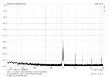
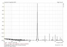
I'm at limits of my measurement equipment, but if I compare the two measurements, once my ADDA loop against my Muses-Pre inserted, I can say that the Muses is not audible or "almost not " visible. But also only quasiperfect.
The noise is not a problem and the distortion factor looks for me well tempered.
Maybe the numbers are still a little better when I use lower sampling rate (22050 not implemented yet in my ADC) and use a very low noise sin-generator, because I measured with my DAC with full bandwidth.
Attachments
You can copy the schematic from our data sheets . (see links)
If you don't like to generate the digital voltage for the muses from the positiv analog voltage, make sure that there is a 10 kOhm in the DVDD line - pin 17.
Spiri, I like your 5V supply better...thank you for the schematic.🙂
I still don't understand when, or when you don't use the 10K resistor on pin 17.😕
The datasheet mentions something about using it to keep too much current from flowing through the 7320 and burning it up.
Last edited:
Using MUSES outputs with unity gain buffers...
When using the 7320 with op-amps on the outputs, the datasheet shows connecting the noninverting inputs to a pair of 10K ohm pots within the IC. That seems to me like it would vary the gain of the op-amps.
Why would you want to do that? What is the purpose of the 10K ohm pots?
If I wanted to use op-amps as unity gain buffers, wouldn't you want to connect their outputs back to the noninverting inputs and forget about the 10K pots in the chips?
I also see where the manufacturer recommends using a couple of nasty 10uF caps on the outputs, which I assume are for DC offset.
Attachments
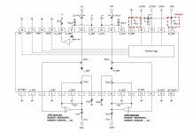
If you don't want/need to adjust the closed loop gain of an opamp then you should connect these pins to GND.
And with modern opamps it should not be a risk to omit this output coupling cap.
And with modern opamps it should not be a risk to omit this output coupling cap.
Spiri, I like your 5V supply better...thank you for the schematic.🙂
I still don't understand when, or when you don't use the 10K resistor on pin 17.😕
The datasheet mentions something about using it to keep too much current from flowing through the 7320 and burning it up.
Read in the datasheet: Current flows when the power [V +] is less than the power [D_VDD].
This could happen if the 5V ramp up faster as the well stabilized V + .
The 10kohm limit the current.
If you don't want/need to adjust the closed loop gain of an opamp then you should connect these pins to GND.
So pins 5,7,10 and 12 should all be grounded and leave out the 10pF caps as well?
You are looking for something like this.
That's cooking for some time
Muses Modular:
stackable up to 8 units or more for multichannel with one external single controller
PADS for input and output
+/-18V header, or install a 78/7915 on the same header
5V Bias for Muses on board
Controller in the same size ore smaller with one board 5V regulator ,without display
rotary encoder or normal potentiometer
IR Receiver
Header for serial interface to configure offset for multichannel and active speaker systems.
learning IR control
Any estimates on cost and time of arrival?
Hi All
sorry to go off topic and report back on the sound😀
it's just sounding better all of the time which must be the break in period mentioned by others.
simply stunning detail and pin sharp imaging.
i'm very happy🙂
sorry to go off topic and report back on the sound😀
it's just sounding better all of the time which must be the break in period mentioned by others.
simply stunning detail and pin sharp imaging.
i'm very happy🙂
Hi All
sorry to go off topic and report back on the sound😀
it's just sounding better all of the time which must be the break in period mentioned by others.
simply stunning detail and pin sharp imaging.
i'm very happy🙂
This must be an error - it's only mid-fi! 😀
This Muses 72320 chip really does sound like a very solid basis for a community effort in making an affordable high-quality pre-amp combining it with one of the ongoing pre-amp projects introduced by Mr. Pass (variants of the BA3 or the LSK pre-amp).
It seems that only little more than the chip itself (available from Mouser), PCBs, some power supplies and an Arduino controller would be required....
It seems that only little more than the chip itself (available from Mouser), PCBs, some power supplies and an Arduino controller would be required....
Any estimates on cost and time of arrival?
We still have to calculate it. I am telling you soon the estimated price.
I get the new Muses in about 12 weeks.
So we have a little time to clarify the interest in this product.
It makes sense to produce at least 50 pieces, because it is a pure diy audio module.
If there is interest, then please go to my commercial thread in the vendor bazaar.
There will be even more information about the progress of the project.
This must be an error - it's only mid-fi! 😀
Ah yes and some of the more gifted amongst us can tell what something sounds like without ever having listened to it.😀
If only I had such abilities then I would save plenty of cash.

Controller in the same size ore smaller with one board 5V regulator ,without display
Since this won't have a display, what is the purpose of the second 5V regulator? Is it to power part of the IR receiver system?
Thanks...
The MUSES chip needs 2 x max.18VDC and additionally 5V
Another 5V is needed for the controller board. If you had a display - this could be fed from 5V-supply of controller
Another 5V is needed for the controller board. If you had a display - this could be fed from 5V-supply of controller
Since this won't have a display, what is the purpose of the second 5V regulator? Is it to power part of the IR receiver system?
Thanks...
5V or 3.3V needed by the controller anyway.
VDD for the Muses is generated from the audio voltage V+ and used for anything else.
Thats my design-goal.
Maybe I use 2 green leds as a shunt instead of the 7805 for VDD.
Maybe consider a more modern regulator? Like LT1963A, LT1761, TPS7A4700, TPS7A3001 etc?Maybe I use 2 green leds as a shunt instead of the 7805 for VDD.
- Home
- Source & Line
- Analog Line Level
- MUSES 72320 electronic volume