By the way
I remember back in the low '80s I had an AES paper called "Electroformers" which were the first Line balancers and receivers to perfectly balance a line, offering Very high CMRR and above that, offering ideal galvanic isolation like transformers.
Unlike the actual Line balancers/receivers which have great specs but perform far less than transformers these electroformers were considered to be challenging for them.
They were designed by Chris Strahm (which is a real nice and competent guy...) from his company at the time CNS Electronics, later changed to ATI (Audio Technologies Inc...not Audio Toys inc.), changed again to LinearX.
If I remember well again, these opamps were used in the Paragon Console he also designed.
They were powered at ±24VDC.
It would have been nice to have these available...
Luke
Last edited:
not quite that old THAT and ATI Ink Exclusive License Agreement
I mentioned differential transmitters/receivers earlier in this thread as one "big hammer" option - these active/op amp based circuits can be cheaper and have higher BW than good audio signal isolation xfmr
if only modest 30dB rejection is needed a differential input can sometimes be implemented with extra feedback parts around the amp stages at even less expense
(buffered/fixed Z analog in is needed)
not quite that old THAT and ATI Ink Exclusive License Agreement
I mentioned differential transmitters/receivers earlier in this thread as one "big hammer" option - these active/op amp based circuits can be cheaper and have higher BW than good audio signal isolation xfmr
if only modest 30dB rejection is needed a differential input can sometimes be implemented with extra feedback parts around the amp stages at even less expense
(buffered/fixed Z analog in is needed)
All these applies only for balanced line which is not my case.
Second...Great basic specs but inferior performance has they offer a too wide bandwidth which is not a good thing when CMRR is decreasing with frequency plus they lack galvanic iso.
Transformers can garantee a minimum of 90dB CMRR over the whole bandwidth but not their electronic counterparts.
Despite this, most of the time it can do the job OK.
But it is not an absolute replacement for transformers.
Luke
Hello
I just finished a 6 channels power amplifier few days ago.
I have a Internal ground loop problem I guess.
I made a test using a generator on each individual channels and they all exhibit excellent noise figure.
But if I connect all six inputs together to the same generator there is a very bad totally unacceptable hum/buzz!
Even with all inputs not connected or even all inputs shorted on six channels, the noise remains.
I tried with 16 ohms resistors between all individual input cable shields and input grounds...no improvement.
And even with 110 pohms resistors no improvement at all.
Any hint to help me someone...?
Thanks
Luke
Hey Luke
Stop f...... around!
Just go with transformers...
You'll be in hell for five weeks if you don't do this.
-"But they are expensive...you're bad...you want to ruin me!!!"
Shut up, you lowlife cheapo...just do it !
Your guardian angel
Last edited:
Hey luke i got the similar problem what you have mentioned and this happened on a strange cause. I was using sommer microphone cable in the beginning and i had absolutely 0 problem but i upgraded to a reference thick cable with shielding and guess what i have got the same problem what you are going through. Im now taking out that cable and rolling back to sommer.
there are few things to consider as Im not a big expert and I dont have great experience in building amps as other forum members are doing. But one thing i would say is..
if you have all those wires floating arround you will definitely endup getting all these sort of issues..
for left channel use one board with just one psu input and use signal guard on the pcb for the signal and use common ground for all as just one trace and connect that trace to the start ground of the psu. Try this but never float those many cables keep it simple and also reg star ground maintain symmetry in it as you will not get any imbalances.
There was a Cinemag Group Buy some years ago.........................
So I checked for Jensen JT-11P-1 and Cinemag CMLI-15-15B.
And my preference goes definitely for Cinemag's....................
I bought six input transformers to be located at the Power Amps feeding the rear channel speakers of surround sound (and other remote amplifiers fed with around the house CAT5).
The difference is between a mono-block (1 channel) and a multiple channel amplifier (2 or more channels).I do not understood why it is so hard to solve the ground problem.
You are not the first people and for sure not the last one that design and made an amplifier with more than 2 channels but seems that which for others works for you does not work.
All the time there are simple solutions and complex solution, cheap solutions and expensive solutions.
It's your choice!
A stereo amplifier falls into the multiple channel amplifier category.
The methods for attenuating interference in going from mono to stereo can be applied to all multiple channel amplifiers.
One has to learn how to build stage1, then how to build stage2 before can can build stage 9 successfully.
http://www.diyaudio.com/forums/soli...ifier-internal-ground-loop-3.html#post3972484
Going to balanced is an alternative route that avoids the learning phase.
Going to balanced is an alternative route that avoids the learning phase.
The more channels you add the more you get in trouble.
An electronic balanced sytem is a good solution but a transformer based one is THE solution.
The solution of my specific problem was in using galvanic iso, not balancing inputs.
Balancing inputs has more to do with relation to outside components than the component they are mounted in.
IMHO...Ground loops with exterior components versus ground loops inside a component, considering my actual experience from this, are two different things.
You can get a huge amount of infos about ground loops and all refers to multi-components relation.
Regarding ground relations inside a component itsefl or even inside a PCboard, very little information and comprehension exists for this subject...a kind of well kept secret of some I would say.
And I can say I had a lot of good suggestions from I really competent people in this forum, suggestions I followed before finally applying "the brutal force concept" by reconstructing my complete Ground system using the "Star-ground" way.
Despite this my problem was still not solved.
But I found to be personnaly sad considering five weeks of experiencing, despite I applied and tested the solution...that I still don't understand why all this happened...
Does someone do finally?
Luke
Last edited:
input transformers is the balanced solution.
Andrew
You're mixing me!!!
What do you mean by "balanced solution"?
It solves a bit here ...a bit there...a bit everywhere...???
Or what?
I'm lost!
😀
Luke
The screened cable is an unbalanced input.
The transformer input is a balanced input.
The transformer output can be either balanced or unbalanced.
Using the balanced input of the transformer avoids the need for all the screens going to the various Sources.
Effectively the transformers have "broken" the loops that the multiple screens created
But I found to be personnaly sad considering five weeks of experiencing, despite I applied and tested the solution...that I still don't understand why all this happened...
Does someone do finally?
Luke
Yes. You placed the supply system directly in the middle of the chassis, and then distributed the low level signal inputs and their grounds in a circle around the only source of 60(50) cycle magnetic field within the chassis.
In my class on "how to successfully generate hum in low signal level equipment", rule number 1 is: Make sure you put the largest generator of 60 cycle magnetic field in the middle, and make sure your grounding structure is designed to trap those fields in loops..
Chapter 2 is entitled "how to complete that ground loop at equipment outside the chassis, so the user has no idea why it only hums when the source completes the ground loops"..
Chapter 3 is titled: "Care and feeding of a magnetic phono cartridge by taping a degaussing coil to the turntable base, and powering it during use"..
Appendix 4 is "Using incendiary devices to finally rid that !@#$%^&&* system of hum" 😡
jn
Everyone has said that there are ground loops in this thing. Wouldn't the fix be as simple as "disconnect this wire to here" then? Why is nobody bringing a specific answer?
I said he should go back to stage 1 and learn to build that correctly.
How more specific can I get.
How more specific can I get.
I think that answer or variations of it have been posted. Breaking the loop is simple when the equipment is in front of you. Remotely, we can only suggest from our experience and the reading of the diagram (which may or may not be always accurate in reflecting the real situation on the ground, pun intended).
We've talked about powering one channel at a time, adding resistance in the input grounds, lifting ground at one end of the cable etc. Sometimes none of these will work because there is still a loop between the PSU at the source and the PSU in the amp, caused by the signal returns going down different paths. It is possible to get hum with one channel. It is possible to have an entirely hum-free system with 7 channels. The solutions are not trivial in either case, and if they are, ala transformers, they are not cheap.
We've talked about powering one channel at a time, adding resistance in the input grounds, lifting ground at one end of the cable etc. Sometimes none of these will work because there is still a loop between the PSU at the source and the PSU in the amp, caused by the signal returns going down different paths. It is possible to get hum with one channel. It is possible to have an entirely hum-free system with 7 channels. The solutions are not trivial in either case, and if they are, ala transformers, they are not cheap.
Yes. You placed the supply system directly in the middle of the chassis, and then distributed the low level signal inputs and their grounds in a circle around the only source of 60(50) cycle magnetic field within the chassis.
In my class on "how to successfully generate hum in low signal level equipment", rule number 1 is: Make sure you put the largest generator of 60 cycle magnetic field in the middle, and make sure your grounding structure is designed to trap those fields in loops..
Chapter 2 is entitled "how to complete that ground loop at equipment outside the chassis, so the user has no idea why it only hums when the source completes the ground loops"..
Chapter 3 is titled: "Care and feeding of a magnetic phono cartridge by taping a degaussing coil to the turntable base, and powering it during use"..
Appendix 4 is "Using incendiary devices to finally rid that !@#$%^&&* system of hum" 😡
jn
JNeutron
1) Yes the supply system is in the middle like majority of amps. Think of a Bryston for instance and llllllllots of other ones!.
So what's the point?
2) No my transformer is near the front panel, aligned in the middle..what's unusual in this?
3) ???
4) Using incendiary devices...what is the problem with transformers specially when used for a solution?
I don't know if I'm right but I understand a bit of irony if not cynicism in the way you express these assumptions.
It is funny but you agreeded my solution of using transformers (post #133) and now you critisize it, seeming to think there was an alternative way to solve this problem.
While you argument in making generalized solutions that almost everybody knows including myself right now, you seem to be unable to pinpoint the exact problem.
Which is inductive and capacitive couplings.
I'm not an expert...in fact this is my first amp from which I learned a lot myself, readings and from the guys here.
My problem was that I start on a too complex project but this is solved and I'm kinda pround of it!
Thanks anyway!
Luke
I think that answer or variations of it have been posted. Breaking the loop is simple when the equipment is in front of you. Remotely, we can only suggest from our experience and the reading of the diagram (which may or may not be always accurate in reflecting the real situation on the ground, pun intended).
We've talked about powering one channel at a time, adding resistance in the input grounds, lifting ground at one end of the cable etc. Sometimes none of these will work because there is still a loop between the PSU at the source and the PSU in the amp, caused by the signal returns going down different paths. It is possible to get hum with one channel. It is possible to have an entirely hum-free system with 7 channels. The solutions are not trivial in either case, and if they are, ala transformers, they are not cheap.
Sangram
Yes like you say...everything has been tried and above.
Every test of configs I did has been noted so I don't repeat them and over more than 140 were noted!
The were no more possible "try this" to implement.
But the transformer solved this...expensive? but less than I first thought and I can reconfig later for balanced inputs at no other cost.
Luke
I don't know if I'm right but I understand a bit of irony if not cynicism in the way you express these assumptions.
Neither.
It is funny but you agreeded my solution of using transformers (post #133) and now you critisize it, seeming to think there was an alternative way to solve this problem.
In your build, I see no other simple method to fix your problem.
You are incorrect. I pointed out exactly what your problem was in response to your direct question. You put the supply in the middle, and distributed amplifier modules essentially in a circle around the power supply. And then, you interconnected every single module with both supply and ground wiring.While you argument in making generalized solutions that almost everybody knows including myself right now, you seem to be unable to pinpoint the exact problem.
Faraday's law of induction is very clear, and very unforgiving when your circuitry invokes it. Your design of course, completed the loop when you hooked up the source.
Which is inductive and capacitive couplings.
Ground loop topologies are generally low impedance, under an ohm or so. Whenever a loop has an impedance below 377 ohms, it will be more susceptible to magnetic induction. When a loop has an impedance greater than 377 ohms, it will be more susceptible to capacitive coupling. Your loop is a hard ground, and you by design placed it full circle around a generator of 60 hz magnetic field.
I'm not an expert...in fact this is my first amp from which I learned a lot myself, readings and from the guys here.
My problem was that I start on a too complex project but this is solved and I'm kinda pround of it!
You should be very proud of what you built. I also found it to be a VERY well made unit. You just got bit by Faraday's law.
You mentioned others put the supply in the middle...while true, they take care to NOT create a conductive loop around the supply which can trap stray 60 hz field. You found this issue out by build.
Never is this a bad thing, as you and others learn from these experiences. You must understand that this ground loop/emc problem is not your's alone. Many very good people have this problem as well. I as well, it's just that I encountered these problems 30 (plus) years ago.
jn
Neither.
In your build, I see no other simple method to fix your problem.
You are incorrect. I pointed out exactly what your problem was in response to your direct question. You put the supply in the middle, and distributed amplifier modules essentially in a circle around the power supply. And then, you interconnected every single module with both supply and ground wiring.
Faraday's law of induction is very clear, and very unforgiving when your circuitry invokes it. Your design of course, completed the loop when you hooked up the source.
Ground loop topologies are generally low impedance, under an ohm or so. Whenever a loop has an impedance below 377 ohms, it will be more susceptible to magnetic induction. When a loop has an impedance greater than 377 ohms, it will be more susceptible to capacitive coupling. Your loop is a hard ground, and you by design placed it full circle around a generator of 60 hz magnetic field.
You should be very proud of what you built. I also found it to be a VERY well made unit. You just got bit by Faraday's law.
You mentioned others put the supply in the middle...while true, they take care to NOT create a conductive loop around the supply which can trap stray 60 hz field. You found this issue out by build.
Never is this a bad thing, as you and others learn from these experiences. You must understand that this ground loop/emc problem is not your's alone. Many very good people have this problem as well. I as well, it's just that I encountered these problems 30 (plus) years ago.
jn
JN
Sorry for my wrong vision of your post and thanks for still carrying on constructive answering!
I just want to understand and learn from this!
Ok now...Like you say, about modules around the supply...
Here is a plan showing electro-physical config of the complete actual amp.
What should have I done instead...two power transformers? ... with primary coils with inverted connections on one transfo maybe 🙂rolleyes:???)...totally independant PSU and RegPSU's...or something else ?
Finally the math part : Was the gain of noise for 6 channels in relation for each channel, like here equivalent to : 20 Log(6²) or something like this?
An externally hosted image should be here but it was not working when we last tested it.
Luke
Last edited:
JN
Sorry for my wrong vision of your post and thanks for still carrying on constructive answering!
No problem. My skills with humor do need work...🙁
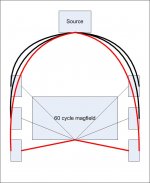
I've drawn up two really rudimentary sketches, so please forgive the "crudity of the model.."
First pic is your design. Note the power grounding, and the input wiring ground layout. I've hilited two input grounds and two power grounds in red. Note the large area formed by that loop.. It will couple to any 60 hz magfield in the chassis.
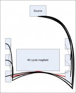
In the second, I pulled the inputs and grounds with my really crude drawing package. Notice there is no loop area anymore. If you go to my gallery, you will find a drawing of three scenario's with a power amp, a source, the IC, and the power cord. Note that the effective solution to my ground loop problem was to eliminate the loop.
Three components are required to get hum.
1. A source of magnetic field. (agressor)
2. A circuit which is sensitive to the currents caused by the loop (victim)
3. A coupling mechanism.
Source can be the transformer, or the wiring itself. Toroids are good at containing field, but the ac wiring must be tightly twisted, loops in the ac can cause magfield. edit: loops in the secondary and the bridge and the wiring all the way to the power supply filter caps can couple as well, so control the currents there as well by twisting both conductors or 3 together.
Low level circuits are by nature, sensitive to the currents, that's another very large topic..edit: the input pair ground reference as well as the ground ref for the feedback divider are two important grounds to worry about.
The coupling mechanism is the proximity of the input ground loop to the source, and the size of the loop.
http://origin.dastatic.com/forums/gallery/data/1875/system_ground_layout_options.jpg
jn
Attachments
Last edited:
- Status
- Not open for further replies.
- Home
- Amplifiers
- Solid State
- Multichannel amplifier internal ground loop