BTW, paralleled pairs of Mouser stock # 660-SPR2CT521R104J will do very nicely for that 50 KOhm LTP anode load, at modest expense. Those parts (supposedly the same as Kiwame) cost 16 cents each. 🙂 Compare that to Michael Percy's price of $6.50 per part for 49.9 KOhm Mills MRA-12s.
Noted!
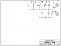
The CL150 inrush current limiter provides but a few seconds delay. Fortunately, that's plenty. Even if the O/P tubes' cathodes are not warmed up, applying a negative voltage to the control grids before B+ rise provides electrostatic protection against cathode stripping.
Eli, what is "Cathode stripping"? I haven't yet bumped into that term.
..Todd
Eli, what is "Cathode stripping"? I haven't yet bumped into that term.
..Todd
The cathode of many tubes, including the KT88, is a metal sleeve coated with oxides that emit large numbers of thermionic electrons, when heated dull red. If the cathode is not hot and emitting, when B+ is applied, the electrostatic field present can literally rip the oxide coating off the metal sleeve.


The phenomenon of cathode stripping becomes more and more important as the anode to cathode differential increases. Below approx. 400 V., cathode stripping is, for the most part, a non-issue. Above 400 V. forewarned is forearmed. Good KT88s are far too dear to gamble with, especially when it's easy to provide the necessary protection.
Eli,
If a 6gk5 or other triode is used instead of the ef86, couldn't we put a CCS for the anode load? i.e. 1045M. With that the gain could be maximized and the operating point easily dialed in to match the operating point of the ltp.
If a 6gk5 or other triode is used instead of the ef86, couldn't we put a CCS for the anode load? i.e. 1045M. With that the gain could be maximized and the operating point easily dialed in to match the operating point of the ltp.
Eli,
If a 6gk5 or other triode is used instead of the ef86, couldn't we put a CCS for the anode load? i.e. 1045M. With that the gain could be maximized and the operating point easily dialed in to match the operating point of the ltp.
You could, of course, use the EF86 in triode with a CCS on top, too. The EF86 sounds great in triode, great in pentode. Nice tube all around.
Good point smbrown.
Can the 12at7 be run at a lower bias to give more headroom for the input tube?
Can the 12at7 be run at a lower bias to give more headroom for the input tube?
Last edited:
Good point smbrown.
Can the 12at7 be run at a lower bias to give more headroom for the input tube?
OK, here's the deal with the 12AT7/ECC81. The type sounds good with a 3 mA. IB and a 200 to 220 V. plate to cathode differential. Sorry, there isn't any wiggle room. AAMOF, it is probably desirable to run at 3.5 mA., which would make things even more difficult. 🙁
It's tough to find reasonably linear triode operating condition sets, when the available anode to cathode differential is only "100" V. Look at the 6GK5 data sheet. I'm considering a 2.5 mA. IB and an IR emitting diode for bias. The opinions of SY and Johan P. are important, at this time.
The EF86 is a WONDERFUL tube, but its triode wired μ is under 30. I fear that insufficient open loop gain will rear its ugly head.
For the record I haven't committed to any method. I do like the idea of having the filaments on a separate transformer, it is not necessary however. I would also prefer to have a PT wound (if a standard winding can't be found) to provide the required voltage for both B+ and bias on the same core. I would also prefer to have a separate winding for the bias and not take it off of the HT out ( or the tubelab style I posted above ).
Using the same core does just like Eli says. Bias is on instantly and B+ comes up a little slower with the inrush limiter.
I believe the Edcor XPR002 meets your requirements above, correct?
Eli,
If a 6gk5 or other triode is used instead of the ef86, couldn't we put a CCS for the anode load? i.e. 1045M. With that the gain could be maximized and the operating point easily dialed in to match the operating point of the ltp.
The "roughed-in" 6GK5 schematic back a few (hundred) posts has a 10M45S as the anode load, with a red LED under the cathode.
If that 98 VA value for the EF86 is correct, I make 50 KOhm LTP load resistors and 6 mA. total LTP "idle" current to be good, when the B+ for the LTP is 460 V.
The above requires that I rethink the 6GK5 operating conditions. I don't like the thought of LTP load resistors less than 50 KOhms, at all. In turn, that means only approx. 100 V. are available at the voltage amplifier anode. My original 6GK5 setup had approx. 200 V. at the anode. Not good!
Eli: The data sheet shows a Va of 135V as the happy place for the 6GK5, with a max Va of 200V. Are these values relevant to this application? I imagine they are.
If I use the boost configuration, the xpwr002 will meet the requirement. We need to keep B+ high enough to allow operating room for the 12at7 LTP. I have asked EDCOR and Jack at Electraprint to quote me the proper xfmr.
I am very interested in what SY and others suggest.
I'll also toss out the idea of using a 6c45p as the front end. mu =52. It likes the lower voltages but would require a decent preamp to drive due to the grid capacitance.
Oh and did I mention that they can oscillate if not implemented correctly ( hence my hesitation to use it )
Last edited:
If I use the boost configuration, the xpwr002 will meet the requirement. We need to keep B+ high enough to allow operating room for the 12at7 LTP. I have asked EDCOR and Jack at Electraprint to quote me the proper xfmr.
I am very interested in what SY and others suggest.
I'll also toss out the idea of using a 6c45p as the front end. mu =52. It likes the lower voltages but would require a decent preamp to drive due to the grid capacitance.
Oh and did I mention that they can oscillate if not implemented correctly ( hence my hesitation to use it )
The 6С45П and 5842 are firecrackers. They come distressingly close to oscillating in the cardboard box. 🙁 These types were engineered for use in grounded grid RF gain blocks. Use in common cathode gain blocks requires the MOST extreme measures imaginable, to prevent parasitic oscillation.
 These sort of tubes are not to be used by inexperienced builders. They can drive you nucking futz. 😡
Eli: The data sheet shows a Va of 135V as the happy place for the 6GK5, with a max Va of 200V. Are these values relevant to this application? I imagine they are.
In order for the LTP to operate correctly, the potential at the voltage amplifier anode must be at or very near 100 V. Go to the 6GK5 plate characteristics graph and move up the 100 V. line. See where it crosses the various grid bias level lines and you get the condition sets available to us. Now, consider the problem of selecting a low voltage, non-resistive, bias part. A NiCd or NiMH cell yields 1.2 V. Among LEDs, types which emit light at shorter wavelengths exhibit "taller" drops. A red LED comes in between 1.5 and 2.0 V. So, an IR emitting type is the only realistic option. SY has considerable experience in implementing diode bias. Both SY and Johan P. have been around the block more times than you can shake a stick at. So, any comments they care to make must be regarded with respect.
Oh and did I mention that they can oscillate if not implemented correctly ( hence my hesitation to use it )
No disagreement.
If I use the boost configuration, the xpwr002 will meet the requirement. We need to keep B+ high enough to allow operating room for the 12at7 LTP. I have asked EDCOR and Jack at Electraprint to quote me the proper xfmr.
This may be a dumb question, but I'm unclear on why we would still need the boost on the Edcor. What's the problem with the head room on the LTP at 460V?
I re-read the first couple of hundred posts and was wondering if there was any other reason for dropping B+ to 465V beside reducing the expense of capacitors? It seems to me that revisiting that may provide a little more room to breath and allow the 12at7 LTP to operate closer to its sweetspot (3.0 to 3.5mA per side and ~220V). At the same time it would make it easier to get Vg to 100V.
I was playing with TubeCad using the classical LTP schematic with only positive power supply. If interested I can post some of the results. It isn't exactly like we are doing since it has a cathode resistor instead of a CCS.
I was playing with TubeCad using the classical LTP schematic with only positive power supply. If interested I can post some of the results. It isn't exactly like we are doing since it has a cathode resistor instead of a CCS.
Last edited:
boywonder,
The XPWR0002 won't develop 465V. Per PSUDII, it will fall in the range of 450V to 455V range when wired normally.
Eli, correct me if I am wrong, but we need the Vg to be about 100V to allow enough swing on the output. Vg will be approximatley a couple of volts more negative than the cathode. If we fix the anode resistor to 50k as the smallest value, it will drop 150V at 3mA. The cathode will be about 100V leaving 210V across the tube. 210V is within Eli's range.
If I understand what Eli was saying about the limit of Ra(anode resistor) 50k is tight considering that Rp is around 20k @ 3mA. Just slightly over 2:1.
If I understand what Eli was saying about the limit of Ra(anode resistor) 50k is tight considering that Rp is around 20k @ 3mA. Just slightly over 2:1.
You have the general idea down, but the situation is actually worse. The net load the 'T7 section "sees" is the parallel combination of the 50 KOhm anode resistor and the KT88 grid to ground resistance. If that grid to ground resistance is substantially less than 100 KOhms, things are going to fall apart. Even if the KT88 grid to ground resistance is 100 KOhms, the LTP is at the ragged edge. Fortunately, a comparatively simple solution to the problem is available. 🙂 DC couple an IRFBC20 source follower to each 'T7 plate. Please observe that the crucial high pass pole count does not increase, while KT88 grid to ground resistance ceases to be of concern.
The FET's source actually sets up a few V. below the gate, but using the gate voltage in calculations is fine. The 'T7 plate and the FET's gate are at 310 V. For a 5 mA. ID the source to ground load resistance is approx. 62 KOhms. A trio of 22 KOhm/2 W. parts wired in series seems about right, in a standard value. Mouser part # 660-SPR2CT521R223J, at 16 cents each, meets the need. Oh yeah, a 510 or 1000 Ω Carbon comp. stopper is absolutely essential at each FET gate. FETs are like tubes in so many ways, including the blasted parasitic oscillation.
boywonder,
The XPWR0002 won't develop 465V. Per PSUDII, it will fall in the range of 450V to 455V range when wired normally.
Is there something wrong with the PSUDII model we've been looking at since er... page 3? I've always thought 465V was possible.
..Todd
Attachments
boywonder,
The XPWR0002 won't develop 465V. Per PSUDII, it will fall in the range of 450V to 455V range when wired normally.
Hmm......either something isn't adding up, or I'm not using PSUDII correctly.
One thing that's a little unusual is the 413V offload voltage for the Edcor; that's 15% regulation. I would have guessed it to be better than that.
If I input 413V offload V, 40.3R secondary R, 120V primary, 1.2R primary R into the transformer properties box, PSUD is giving me a transformer with 413V/54.5R, which easily gets 500+ volts B+ if we want it, although I'm not sure I believe the numbers.
Using 360V/54.5R transformer properties barely makes 450V depending on choke R, and using 360V/40.3R yields a B+ of 458V with the same choke as above. Both of the above are with CLC=47u-10H/63R-330u.
Using 360V/40.3R with a hammond 5H/26R (193P) choke yields 464V B+.
Last edited:
- Home
- Amplifiers
- Tubes / Valves
- Mullard 5-20 KT88 PP blocks!