Eli, I think you are talking about a using the winding as a bucking transformer. If so I don't think PSUII will sim that.
The idea behind that is the 6.3 winding will kick-up the magnetic flux in the core resulting in an increased output on the secondary windings. There was some threads on this a while back. Will have to see if I can find them
The idea behind that is the 6.3 winding will kick-up the magnetic flux in the core resulting in an increased output on the secondary windings. There was some threads on this a while back. Will have to see if I can find them
Last edited:
Eli: How do we boost the primary V? Not quite getting it....
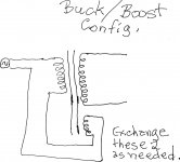
Wire a "6.3" V. winding in series with the paralleled primaries. Of the 2 possible arrangements, 1 will increase the rectifier windings' O/P and the 2nd will reduce the O/P. These are known, respectively, as the boost and buck configurations. Obviously, we're interested in the boost configuration. Simple measurements, with a multimeter, will let you know when things are in order.
The line voltage doesn't change, but the effective turns ratio does. 😉
boost and buck
Taj: Although Antek lists the primary at 115V, the test data on the datasheet was conducted at 120V, and that's what I used in the model, so I'm assuming we've already collected those volts.
Eli: Got it. So will we get another 7V X 3x=21V or so at the output? That'll work easily. I'll re-model this config.
SGregory: Got it thanks. I'll revise and post shortly. Please feel free to also PSUD this as another set of eyes (and a brain) couldn't hurt.
The electric company is boosting the primary input (on your behalf) to 120v rather than 115v, so output (with the series winding) is about 370v before rectification, and 481 after.
[edit] Though I think this isn't what Eli was talking about.
..Todd
Taj: Although Antek lists the primary at 115V, the test data on the datasheet was conducted at 120V, and that's what I used in the model, so I'm assuming we've already collected those volts.
Eli: Got it. So will we get another 7V X 3x=21V or so at the output? That'll work easily. I'll re-model this config.
SGregory: Got it thanks. I'll revise and post shortly. Please feel free to also PSUD this as another set of eyes (and a brain) couldn't hurt.
Eli, is this what you are thinking about? I couldn't link directly to it so I just attached the pdf on the thread. Thanks zigzagflux. Actually backwards from the pdf. It will also boost our bias voltage too.
Boywonder, I will follow through with PSUDII. I can get up to 465 with C1 at 220uf. But I think it is too hard on the diodes. The question is what do we want for acceptable ripple? I'll post the model output shortly when I add the right values in.
Boywonder, I will follow through with PSUDII. I can get up to 465 with C1 at 220uf. But I think it is too hard on the diodes. The question is what do we want for acceptable ripple? I'll post the model output shortly when I add the right values in.
Attachments
Last edited:
Boywonder, Using a 720VCT my sims confirms yours. about 453V. Although using a 5H 93R choke and 120uf/330uf for C1 and C3 I get 7.9mV ripple.
Using the 6.3V winding will work. I have seen others use it to let them apply a xfmr they had laying around
Using the 6.3V winding will work. I have seen others use it to let them apply a xfmr they had laying around
Correction to post #464 I cannot get 465V with 220uF at C1. Had wrong dcr for transformer at the time.
Do we still need to fit the choke inside the chassis? I think it to be important to have at least 5H R1 should also be at least 400R.
In the sim I have a 370-0-370V with 39.5R DCR. Using same cap values from posted schematic and a 5H 100R choke. (my last electra print measured close to this) and 400R R1, I get the following values:
Vb1 = 466.7 7.44mV ripple Vb2= 460.7 620uV ripple Vb3=257V 2.6uV ripple.
150mA KT88 12mA 12at7 3mA ef86
If you use the boost configuration, Vb1 will run up to 486V without increasing dcr of choke. R1 needs to be increased as well unless running the LPT at a higher b+ is desireable. (using the ANtek mentioned above)
Correction to post #464 I cannot get 465V with 220uF at C1. Had wrong dcr for transformer at the time.
Do we still need to fit the choke inside the chassis? I think it to be important to have at least 5H R1 should also be at least 400R.
In the sim I have a 370-0-370V with 39.5R DCR. Using same cap values from posted schematic and a 5H 100R choke. (my last electra print measured close to this) and 400R R1, I get the following values:
Vb1 = 466.7 7.44mV ripple Vb2= 460.7 620uV ripple Vb3=257V 2.6uV ripple.
150mA KT88 12mA 12at7 3mA ef86
If you use the boost configuration, Vb1 will run up to 486V without increasing dcr of choke. R1 needs to be increased as well unless running the LPT at a higher b+ is desireable. (using the ANtek mentioned above)
I reached the same conclusion for the value of R1 this morning....470R would be better than 220R. I've been using/assuming 6ma total for the 12AT7 (3ma/side). Is it actually 6ma/side 12ma total?
I agree on the choke value also, Tubemack was hoping to put the choke under the hood, but 5+ henries makes choke current rating and ripple a little less.
For 60hz mains, the choke needs to be sized for the DC current + the ripple current, approximated by Vrms/(1386L)
so for a 2.5H choke, we need a choke rating of at least 218ma + 360/(1386*2.5)= 321 ma
for a 5H choke, we need at least 218ma + 360/(1386*5)= 270 ma
Eli, is this what you are thinking about? I couldn't link directly to it so I just attached the pdf on the thread. Thanks zigzagflux. Actually backwards from the pdf. It will also boost our bias voltage too.
Boywonder, I will follow through with PSUDII. I can get up to 465 with C1 at 220uf. But I think it is too hard on the diodes. The question is what do we want for acceptable ripple? I'll post the model output shortly when I add the right values in.
Please refer to the crude graphic I've uploaded. There are 2 possible arrangements for connecting the low voltage winding. One increases the voltage observed at the rectifier winding, while the 2nd decreases it. Use a meter to obtain the desired boost configuration.
Attachments
You are right. I saw 6mA and doubled it. 470R would then be more reasonale. Would then drop r3 as needed for voltage.
Thanks Eli, that is much better than what I found. With that you could make either the ANtek or the Edcor xpwr002 work
Thanks Eli, that is much better than what I found. With that you could make either the ANtek or the Edcor xpwr002 work
Last edited:
fun with windings
Got it Eli, thanks. Now we need someone to buy one of these, connect it up and get the offload V and primary and secondary R's for the model. If the other 6V tap is to be used for bias voltage multiplication, then a separate filament transformer will be req'd.
Or, alternatively, use the other filament winding for the heaters, and get a separate bias transformer like an Amveco 70035 or 62035, etc.
Please refer to the crude graphic I've uploaded. There are 2 possible arrangements for connecting the low voltage winding. One increases the voltage observed at the rectifier winding, while the 2nd decreases it. Use a meter to obtain the desired boost configuration.
Got it Eli, thanks. Now we need someone to buy one of these, connect it up and get the offload V and primary and secondary R's for the model. If the other 6V tap is to be used for bias voltage multiplication, then a separate filament transformer will be req'd.
Or, alternatively, use the other filament winding for the heaters, and get a separate bias transformer like an Amveco 70035 or 62035, etc.
Mixing primary and secondary winding on a power transformer connected to the mains... 😱
I think it's best Bud step in and advice you guys, I would not do that from a safety measure point of view.
And please consider the following way of modding a toroid if you want to adjust secondary voltages (note this description applies to secondary only of safety measure even if it can be applied to primary as well) as I described here:
http://www.diyaudio.com/forums/tubes-valves/156699-mullard-5-20-kt88-pp-blocks-21.html#post2083334
Within certain limits this is a safer measure, read Buds "Choosing an OPT" where he recently went to a length describing how to design a transformer that also conforms with safety regulations regarding design layout and materials.
Cheers Michael
Last edited:
Or, alternatively, use the other filament winding for the heaters, and get a separate bias transformer like an Amveco 70035 or 62035, etc.
No go! Like the rectifier winding, the remaining filament winding will be boosted. Voltage multiply that voltage, whatever it turns out to be, to obtain all negative rails needed. A separate filament trafo is a must, but SGregory wants to go that route, no matter what. I suspect he is planning some sort of power on sequencing.
sir, your winding is boosted...
Got it Eli......still absorbing. That appears to be the downside of boosting the primary, all secondaries are affected.
Ultima Thule brings up a good point, and I know it's been brought up before with regard to some of Poindexter's designs.
We're not after a UL sticker, but folks should be aware of the intermingling of the primary & secondary winding (you lose some isolation between the windings).
I also like the start up sequencing idea, but it adds a little complexity here....and one typically wants the heaters and the bias voltage up before the B+, which requires 3 separate transformers.
Last edited:
The heaters can start up 1st, without any trouble whatsoever. What's VERY important is bias being applied before B+ rise. The CL150 inrush current limiter provides but a few seconds delay. Fortunately, that's plenty. Even if the O/P tubes' cathodes are not warmed up, applying a negative voltage to the control grids before B+ rise provides electrostatic protection against cathode stripping. Having the bias winding on the same core as the HT winding is fine, as the bias supply is "instant" on.
If the tranny has the 5V for the rectifier you could use that instead of the 6.3V. The only issue would be that the 6.3v for the heater would be boosted as well. (maybe too much for the filament.) With the seperate bias xfmr, you will want to interlock the b+ to the bias else all sorts of nasties are possible.
Yet another possibility would be to split off of the primary at the xfmr before the diodes and rectify for the negative bias (tubelab SE style). With a solid voltage divider we could get the -55V. Throw a good quality bypas cap in and it would even have low impedance for a2 operation.
Not that I have ADD or anything, but what should the grid bias voltage of the ltp be? Based on my understanding it should be around 98V per the schematic.
Last edited:
Michael,
Thanks for pointing that out. I havn't calculated the operating point yet myself so I just used your number. Even when I do, with todays tubes I'll be lucky to have it even close to what the sheets say it should be.
Thanks for pointing that out. I havn't calculated the operating point yet myself so I just used your number. Even when I do, with todays tubes I'll be lucky to have it even close to what the sheets say it should be.
For the record I havn't commited to any method. I do like the idea of having the filaments on a separate transformer, it is not neccesary however. I would also prefer to have a PT wound (if a standard winding can't be found) to provide the required voltage for both B+ and bias on the same core. I would also prefer to have a seperate winding for the bias and not take it off of the HT out ( or the tubelab style I posted above ).
Using the same core does just like Eli says. Bias is on instantly and B+ comes up a little slower with the inrush limiter.
The sequencing would be easy enough. Put two switches in series. tie the filament transformer in after the first switch. The PT is tied to the second switch. This way the PT can't be switched on before the filaments xfmr is on. The worst case would be that they come on together if the PT was left in the "on" position.
Last edited:
Someone should contact the transformer engineers for those two powers and confirm that they have provided reinforces insulation from the safety low voltage secondary to the hazardous voltage secondary, which would include and rectifier filament windings that go along with the B+ secondaries.
Keep in mind that the dielectric withstand of the 6.3 volt filament winding will see the peak opposite polarity voltages across that barrier from 6.3v filament to plate and if the dielectric barrier is not a reinforced one you might want to be very careful about making that particular transformer your long term power supply transformer.
For a short period of time, assuming they do meet modern UL and CE 6500 insulation standards I don't see any particular danger. But, you really do want to confirm that particular insulation barrier strength. I see no reason why they would refuse to discuss it with you, whereas they might be reluctant to do so with me.
Bud
Not that I have ADD or anything, but what should the grid bias voltage of the ltp be? Based on my understanding it should be around 98V per the schematic.
In a Mullard style amp, the LTP is DC coupled to the voltage amplifier anode. Therefore, the LTP grids must be at the same DC potential as that anode, with respect to ground. Of the 3 quantities: IB, plate to cathode differential, and cathode to grid differential, any 2 define the 3rd. The LTP grid potential is known. The CCS in the LTP's tail forces IB to be known. Knowing the B+ rail voltage and the LTP load resistor values makes VA, with respect to ground, known. Perforce, the LTP cathodes will set up where they must. As long as enough Volts are present to operate the CCS and provide cathode compliance, all is well. SY was kind enough, early on in this thread's "life", to do the math needed to eliminate a B- rail under the LTP CCS.
If that 98 VA value for the EF86 is correct, I make 50 KOhm LTP load resistors and 6 mA. total LTP "idle" current to be good, when the B+ for the LTP is 460 V.
The above requires that I rethink the 6GK5 operating conditions. I don't like the thought of LTP load resistors less than 50 KOhms, at all. In turn, that means only approx. 100 V. are available at the voltage amplifier anode. My original 6GK5 setup had approx. 200 V. at the anode. Not good!
BTW, paralleled pairs of Mouser stock # 660-SPR2CT521R104J will do very nicely for that 50 KOhm LTP anode load, at modest expense. Those parts (supposedly the same as Kiwame) cost 16 cents each. 🙂 Compare that to Michael Percy's price of $6.50 per part for 49.9 KOhm Mills MRA-12s.
- Home
- Amplifiers
- Tubes / Valves
- Mullard 5-20 KT88 PP blocks!