We should then bring ourselves to setting up the required operating points.
Lets define specificaly what we want out of the kt88's and what drive will be required to get them there. We should probably summarize and consolidate the specs in the next few responses. I myself am a little lost as this thread is getting long with alot of great input.
If I understand the thread so far B+ 465V, 50-60W, at 75mA Bias. What is the drive voltage swing and power required?
The LTP as it stands is 460VB+. I think we are still seeing if this will work with the loads present.
The Input tube is still up in the air between the ef86(pent) and 6GK7(triode).
For the input tube, we've pretty much considered two versions. TubeMack wants the EF86 (and it's his thread, which is always worth respecting), but others, myself included, would like to pursue the 6GK5 with CCS load at the input. So two versions have been running concurrently.
I think the challenge has been to determine the 3 tube operating points together with a B+ scheme that suits everything. All power supply discussions should naturally come after that is resolved. My feeling is that we should completely ignore power supply implementation concerns until after the amplifier has its voltage structure determined. Then determine how best to tackle those requirements. The power supply discussion has been a big multi-tangential distraction to the thread, since it's aiming at a moving target.
..Todd
Last edited:
Agreed. I am ok with either input as well. I am interested in the pentode as I have never worked with one before and it would be a GREAT learning experience. If we do this right, switching back and forth should be a simple MOD later.
In either case the operating conditions will have to be set up based on what the LTP requires to drive the kt88. Lets get back to that discussion.
Power supply tangent probably my fault. Sorry about that.
Not to be backwards from what I said above but I propose that we do as Eli suggested and set the requirement for Vg to be 100V minimum and still be able to drive kt88 load.
One Question, Can GNFB be injected into the cathode of a LED biased triode? Seems to me that we would be shunting it to ground.
The LTP as it stands is 460VB+. I think we are still seeing if this will work with the loads present.
Yes, it will work. 50 KOhm load resistors are fine for a 12AT7 LTP, if the grid to ground resistance of the "finals" is reasonably high. We used 470 KOhms in "El Cheapo" and everything hangs together quite nicely. We are confronted in this "fixed" bias situation with a 100 KOhm grid to ground limit. Put MOSFET buffers in that are DC coupled to the LTP anodes and all will be well. Now, a KT88 grid to ground resistance considerably less than the 100 KOhm limit is a non-issue. The down side of making the KT88 grid to ground resistance really low is the large value needed for the coupling capacitors. The coupling cap. and grid to ground resistance form a high pass pole. Good performance requires F3 of that pole be <= 5 Hz. 330 nF. is good into 100 KOhms. As the resistance decreases, the coupling cap.'s value must rise.
One Question, Can GNFB be injected into the cathode of a LED biased triode? Seems to me that we would be shunting it to ground.
No problem! The NFB setup is a voltage divider. The ground side of the bias setup, be it a RC network or a LED, connects to the divider's tap. Among my earliest 6GK5 remarks, I stated that the resistance to ground needs to be kept small, say 22 Ω. Otherwise, the drop across that resistance throws the bias voltage off.
Eli,
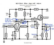
Thank you for being patient with me. I attached a schema that shows what I think you mean regarding inserting the GNFB. If correct that makes sense to me and I also see where your comment came from earlier in the thread. I associated 22R with the cathode resistor of the kt88 as in the schematics.
Please discount the FET arrangment shown. I havn't drawn the version you are describing yet. I was playing with the powerdrive for grins and giggles. I am not set on it, just considering it. It requires a solid negative bias rail but does have the advantage of being able to use a smaller coupling cap. I also don't think A2 is an issue since there is only a marginal swing into A2 from the ltp. ASSUMING my calculations are correct using tubecad.
ALSO the CCS's are drawn using a fet symbol since VISIO doesn't have a CCS icon
Attachments
Eli,
Thank you for being patient with me. I attached a schema that shows what I think you mean regarding inserting the GNFB. If correct that makes sense to me and I also see where your comment came from earlier in the thread. I associated 22R with the cathode resistor of the kt88 as in the schematics.
Please discount the FET arrangment shown. I havn't drawn the version you are describing yet. I was playing with the powerdrive for grins and giggles. I am not set on it, just considering it. It requires a solid negative bias rail but does have the advantage of being able to use a smaller coupling cap. I also don't think A2 is an issue since there is only a marginal swing into A2 from the ltp. ASSUMING my calculations are correct using tubecad.
ALSO the CCS's are drawn using a fet symbol since VISIO doesn't have a CCS icon
That graphic looks about right, but put stoppers on the FETs' gates. Even if the amp stays AB1, an advantage to that sort of circuitry is immunity to blocking distortion. However, PSU complexity is the price to be paid.
While the situation is quite different, the phono preamp schematic I've uploaded shows how you DC couple a FET to a triode's plate. If this style is used and the KT88 grid to ground resistance is 47 KOhms, the coupling cap. should be 680 nF. or greater. A 1 μF. part would kick some butt.
Attachments
OK, stoppers on the FET, forgot them.
I'll sketch up your version tomorrow when I get a little free time.
May I ask what the complexity of the PSU will be? I see both versions needing a negative bias rail which would be coming off of its own winding.
Also for tubemak, taj, boywonder, and others, using the FET (either version) in this application really works well. If I may suggest we should incorporate a version of this into the design. Having unity gain it adds little signature if any to the sound, and eliminates the problems with using the t7 at these voltages and loads from the kt88. It will also allow the kt88 to have a better value for grid leak resistor
What say you?
Last edited:
Please discount the FET arrangment shown. I havn't drawn the version you are describing yet. I was playing with the powerdrive for grins and giggles. I am not set on it, just considering it. It requires a solid negative bias rail but does have the advantage of being able to use a smaller coupling cap. I also don't think A2 is an issue since there is only a marginal swing into A2 from the ltp........ Even if the amp stays AB1, an advantage to that sort of circuitry is immunity to blocking distortion. However, PSU complexity is the price to be paid.
I have been following this thread, reading it every other day or so. I think you guys are on the right track, and it seems that the last thing needed is another different voice. I can say that it is possible to get 75 watts out of a pair of EH KT88's in TRIODE mode with a 2500 ohm load with a 450 volt supply in AB2 using PowerDrive. Power was 50 to 60 watts with a 3300 ohm load. Triode sounds good enough to run the amp with zero GNFB.
There seems to be a few opinions about the power supply, so I will just throw this idea out there. I don't like the buck / boost idea either. I am using an Antek 4TK400 power transformer in my amp. One transformer runs both channels. The heater windings are not sufficient for both channels, but it looks like you guys are looking at a seperate heater transformer anyway. Why the 4TK400? Because it has a 70 volt tap on both HV secondaries. With the two secondaries wired in series like the typical power transformer, you get a 400-70-0-70-400 volt winding. Ground the center tap, and run the two 70 volt windings into a SS bridge rectifier to get +90 volts DC for the PowerDrive fet drains and -90 volts DC for the bias, LTP tails, and PowerDrive fet sources. SS rectification allows for instant bias voltage. The 400 volts go to the plates of 3 different 5AR4's. WTF? Yes, one 5AR4 for the B+ in each channel feeding its own choke input filter. The 3rd 5AR4 runs a capacitor input filter that feeds the LTP's for both channels all of the voltage that they can eat.
The seperate rectifiers provide nearly as much isolation as seperate power supplies. A single 5AR4 doesn't have the current handling capability to run both channels.
May I ask what the complexity of the PSU will be? I see both versions needing a negative bias rail which would be coming off of its own winding.
Look at DC coupling to the plate again. The FET's drain goes to B+. The FET's gate (through a stopper) goes to the LTP section plate. The FET's source goes to the grounded load resistor and the interstage coupling capacitor. The FET is powered totally from the same points the LTP is powered. 😀 There's no muss or fuss and it's reasonably "idiot resistant". Nothing is "idiot proof".

Don't forget the grounded wrist strap, when handling MOS semiconductor parts.
Also for tubemak, taj, boywonder, and others, using the FET (either version) in this application really works well. If I may suggest we should incorporate a version of this into the design. Having unity gain it adds little signature if any to the sound, and eliminates the problems with using the t7 at these voltages and loads from the kt88. It will also allow the kt88 to have a better value for grid leak resistor
What say you?
I'm in.
6GK5s, FET coupling, CCS, UL or trioded KT88's.....I'm all over that, but we are wandering away from TubeMack's original goal of a monoblock 5-20 design. For the traditionalists, we have sand creeping in all over the place, which may give them hives........
If the FETs get voted off of the island, that discussion could be continued in chrish's 6L6GC AB2 thread......
Last edited:
I don't mind FETs in the design. But it does complicate the construction as a DIY project. Not for me necessarily, but it almost implies PCBs. And PCB's don't bother me either, as long as someone is willing to work with me to design a PCB layout when the time comes.
Tubelab, I (for one) appreciate the input. Feel free to chime in whenever you feel the urge. 😉
..Todd
Tubelab, I (for one) appreciate the input. Feel free to chime in whenever you feel the urge. 😉
..Todd
Last edited:
Two FET Schemes
Attached is the AB1 schematic and the corrected AB2 schematic.
Same issues apply with the CCS's, I havn't made a CCS symbol yet.
Also note I put the RC network in the anode supply of the driver, Only for future discussion as I don't know if it is warranted, or a bad thing. The original Mullard had it on the EF86 for better HF stability.
Attachments
I have been following this thread, reading it every other day or so. I think you guys are on the right track, and it seems that the last thing needed is another different voice. I can say that it is possible to get 75 watts out of a pair of EH KT88's in TRIODE mode with a 2500 ohm load with a 450 volt supply in AB2 using PowerDrive. Power was 50 to 60 watts with a 3300 ohm load. Triode sounds good enough to run the amp with zero GNFB.
Personally, I don't mind the FET creeping into the design so long as we offset with triode and no GNFB as suggested. To me, sounds like one down, two up.
hey-Hey!!!,
On the power drive, the source follower can also be a cascode arrangement. It then delivers a very stable input capacitance with no loss of drive capability for additional complexity( that is IMO quite worth it ). I've found that even when running MOSFET's well into their stable gate capacitance region their sonics were not up to the level offered by the cascode.
cheers,
Douglas
having just 3 terminals, i see no reason why you can't use fets using p2p wiring...
Indeed you can. I have PTP wired fets in tube circuits even though I tend to use PC boards in any design where I might make more than one copy. When PTP wiring mosfets include a gate stopper resistor (missing from the AB2 schematic) right at the gate terminal of the mosfet. Slipping a small ferrite bead over the lead won't hurt either.
The AB1 schematic will work, but it misses the main point of mosfet grid drive. Overload recovery. Any time you drive the grid of an output tube with the typical coupling cap - grid resistor circuit, you will be succeptable to "blocking distortion". In an amp where the power capabilities are far greater than the average listening level this may not be much of an issue. I have recently spent some time listening to an RC coupled amp that makes from 90 to 200 WPC depending on which tubes I use, and I must say the word "effortless" comes to mind. There is just no way I can clip this amp too often without my speakers catching fire!
The AB2 design needs gate stoppers on the mosfets. It shuold work as drawn (with stoppers). Running the mosfet drains directly from the B+ supply means that they will dissipate some considerable power and require a heat sink. That is why I prefer to use a seperate positive voltage source of 50 to 100 volts. I usually use a seperate small transformer to generate + and - supplies, until I found the big Antek 4TK400. It has the taps for this already.
The thread that was detailing our amp build has temporarilly cooled off since neither of us has time to work on our amps right now.
I thought I put the gate stoppers in the schematic. Actually I did, just never made a new pdf. Here you go.
George, what kind of current in the FET's? Even at 3mA, I calculated it would need a heat sink in this configuration.
Good word "Effortless". It explains my experience when playing with some breadboard SET amps a short while back with and without a low impedance drive.
George, what kind of current in the FET's? Even at 3mA, I calculated it would need a heat sink in this configuration.
Good word "Effortless". It explains my experience when playing with some breadboard SET amps a short while back with and without a low impedance drive.
Attachments
Last edited:
George, what kind of current in the FET's? Even at 3mA, I calculated it would need a heat sink in this configuration.
I tend to run 10 to 20 mA through the mosfets. They seem to like more than 3 mA, but I don't find any difference over 10 mA, unless you are using them for screen drive. Some users claim that a CCS load instead of a resistor in the source lead sounds better, and some claim that a cascode or bootstrapped arangement is better. I have tried both and found that the results weren't worth the effort if you start with the right mosfet.
Good word "Effortless".
And I am using that word in reference to an amp that I didn't design, that uses all pentodes, and no GNFB! I took Pete Milletts "engineers amp" and cranked it up to some extreme power levels.
- Home
- Amplifiers
- Tubes / Valves
- Mullard 5-20 KT88 PP blocks!