But where is the DC coming from?
It's not there without U401 in place. There is no feedback for the pin 1 to pins 2 and 3. I've been trying to find anything that would cause output there and I haven't found it.
Does the amp produce audio?
It's not there without U401 in place. There is no feedback for the pin 1 to pins 2 and 3. I've been trying to find anything that would cause output there and I haven't found it.
Does the amp produce audio?
There are no output fets installed. The amp came in with no fets. Do you perhaps also know which output fets should be used in this amp?
The measurements taken from last posts are taken with the diode D402 still out of the circuit.
I will re-install D402 and measure, remove U401 and take some new measurements to try to find the causing for the DC offset.
The measurements taken from last posts are taken with the diode D402 still out of the circuit.
I will re-install D402 and measure, remove U401 and take some new measurements to try to find the causing for the DC offset.
I don't know which FETs were used in this amp. The IRFP240 was used in a smaller MTX amp. The FDA59N25 was used in a Sundown amp that was similar in design. Someone else may have a more definitive answer.
So, I took out U401.
(D402 not installed)
U401 pads:
Pin 2 1.65v DC
Pin 3 0.08v DC
Installed D402
U401 pads:
Pin 2 1.12v DC
Pin 3 0.6v DC
So, the DC offset is not caused by U401
(D402 not installed)
U401 pads:
Pin 2 1.65v DC
Pin 3 0.08v DC
Installed D402
U401 pads:
Pin 2 1.12v DC
Pin 3 0.6v DC
So, the DC offset is not caused by U401
Connect a load across the terminals.
Does the voltage drop to 0v?
Do you lose the offset on the op-amp?
Does the voltage drop to 0v?
Do you lose the offset on the op-amp?
Hmmm, offset gone, there is a clean square wave now.
Is this normal for MTX amps to not produce a PWM signal when there is no load connected?
Would a FDA24N40F fit for testing?
Is this normal for MTX amps to not produce a PWM signal when there is no load connected?
Would a FDA24N40F fit for testing?
That FET should work.
I have never tried troubleshooting without the FETs in the circuit. Problems with shorted outputs was rare.
I have never tried troubleshooting without the FETs in the circuit. Problems with shorted outputs was rare.
Output fet switching seems to work, I soldered one fet per bank (2 banks).
Idle current draw is pretty high, about 3.8A at 12.6v. U401 heats up pretty much, output inductors get quite hot.
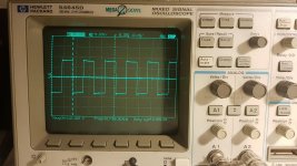
The fet switching seems very clean for one fet per bank.
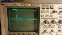
Unfortunately there is a perfect triangle wave on the + terminal (photo attached)
Other photo attached is the output fet switching.
Idle current draw is pretty high, about 3.8A at 12.6v. U401 heats up pretty much, output inductors get quite hot.
The fet switching seems very clean for one fet per bank.
Unfortunately there is a perfect triangle wave on the + terminal (photo attached)
Other photo attached is the output fet switching.
Attachments
The inductor and U401 heating are normal.
The triangle waveform is residual from the carrier waveform. That's not a problem.
Does the amp produce audio?
Don't operate the amp without having ALL semiconductors tightly clamped down.
The triangle waveform is residual from the carrier waveform. That's not a problem.
Does the amp produce audio?
Don't operate the amp without having ALL semiconductors tightly clamped down.
I measured 63 degrees at U401 and 73 degrees at the output inductors.
Is this a normal temperature?
The amp produces audio. I have not tried over 10 watts, since there is a load connected and only one fet (clamped down).
I will solder some fets in.
Is this a normal temperature?
The amp produces audio. I have not tried over 10 watts, since there is a load connected and only one fet (clamped down).
I will solder some fets in.
I never measured the temperature but I know the inductors will get too hot to hold continuously.
The op-amp is very nearly driving a 100 ohm load at full rail to rail (±15v) continuously. Not a great design but it's generally reliable.
I'm sorry that I missed where you stated that all of the outputs were out of the circuit. That wasted some time.
The op-amp is very nearly driving a 100 ohm load at full rail to rail (±15v) continuously. Not a great design but it's generally reliable.
I'm sorry that I missed where you stated that all of the outputs were out of the circuit. That wasted some time.
Please, don't apologize 🙂
I think you are the last person on this forum who ever needs to give an apology. I'm very very grateful for your big effort to help all of us techs.
Ahhaa, that's a very stressfull load. If I would be the engineer I would clamp it to a heatsink or cooling fan. I will place an extra cooling fan over the drive circuit to make sure it's more reliable in the future.
I plugged in the filter board (I tested with jumper wires before). I get no sound out of it. Also the light does not work on the filter card. I do measure +-15v and +-12v on the jumper wires.
Also, LED400 and the service LED is still on. Current pull with all fets in is 4a at 12.6v
Strange, because the output fets barely / dont heat up.
Last edited:
With the preamp jumpers in place (instead of the preamp board), do you get audio?
Did any of the regulators fail in this amp?
Did any of the regulators fail in this amp?
I do get audio with jumpers. Not incredible loud, but at least some watts.
I tested FET191 and FET192, I measure +-15v there.
FET401 measures -60v to GND on Pin1 and Pin3
U102 measures 5V
I tested FET191 and FET192, I measure +-15v there.
FET401 measures -60v to GND on Pin1 and Pin3
U102 measures 5V
Did you have to repair any of the regulators?
FET401. Is that the FET adjacent to FET192? If so, that's likely the regulator for one of the optocouplers. Confirm that you read approximately 18v from pin 5 (black) to pin 8 for both optocouplers.
FET401. Is that the FET adjacent to FET192? If so, that's likely the regulator for one of the optocouplers. Confirm that you read approximately 18v from pin 5 (black) to pin 8 for both optocouplers.
Correct, FET192 is adjacent to FET401
I did not have to repair any of the regulators, allthough, someone else did.
Soldering is not factory standard.
One optocoupler reads 19.2v and the other reads 20.2v as VCC
I did not have to repair any of the regulators, allthough, someone else did.
Soldering is not factory standard.
One optocoupler reads 19.2v and the other reads 20.2v as VCC
Those voltages are OK. You have to read FET104's source referenced to the negative rail. No need to re-check.
You could have a dirty switch or pot on the preamp board. If not, look for burned 10 ohm resistors (check all with meter) on that board.
You could have a dirty switch or pot on the preamp board. If not, look for burned 10 ohm resistors (check all with meter) on that board.
R112 and R111 was burned. Changed it for a new one, it burns down again.
One side has +15v and the other side -15v
One side has +15v and the other side -15v
Last edited:
- Home
- General Interest
- Car Audio
- MTX Thunder 81001 component value/schematics