I've never seen anything like this.
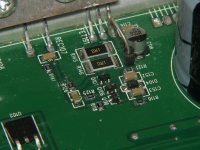
In some of these amps, they started to add the Zener shown on FET191 that helped to protect the components on the board when the regulator failed (which was a common problem). This could not have worked if this was the negative regulator.
In some of these amps, they started to add the Zener shown on FET191 that helped to protect the components on the board when the regulator failed (which was a common problem). This could not have worked if this was the negative regulator.
Attachments
On the other side of the board (at C118) where the negative rail rectifiers are installed, is a zener diode like that installed as well.
To clarify... you're saying that the regulator with the Zener is the negative regulator (has negative rail voltage on R145/146?
As this makes totally no sense, and this seems very strange, I think that my scope's channel possibly might be on reversed polarity due tue a previous differential measurement.
But, the readings that I had on FET191 were:
Pin1: strange waves +-39V DC
Pin2: clean -82v rail voltage
Pin3: sawtooth wave looking +-29v DC
If the scope was reversed, this means all readings from above would be reversed too.
Which means FET191 would have 2x negative voltage on the legs and a positive rail voltage.
I will check again later today when I'm back home. I will send more photo's of the board and double check the voltages.
Last edited:
So, as I expected, the probe signal was still on invert.
I did some previous measurements again.
FET191
Pin 1: strange wave -44.1v
Pin 2: +82v
Pin 3: strange wave - 32.2v
Q110
Base:-32.2v
Collector: 82v
Emitter: strange triangle -32.7v
I did some previous measurements again.
FET191
Pin 1: strange wave -44.1v
Pin 2: +82v
Pin 3: strange wave - 32.2v
Q110
Base:-32.2v
Collector: 82v
Emitter: strange triangle -32.7v
Attachments


No, C119 reads about 5k (slowly rising above 5k sometimes, slowly rising under 5k sometimes. Both C119 terminals.
C118- reads about 4.5k to GND
C118+ reads about 55k
C118- reads about 4.5k to GND
C118+ reads about 55k
What resistance do you read to the negative speaker terminal?
What voltage do you read when you measure directly across C118 and C119?
What voltage do you read when you measure directly across C118 and C119?
Same readings to negative speaker terminal. Hard to check precisely since the value is not constant, but it's in the same range.
C118 reads 15.5v
C119 reads 15.1v
C118 reads 15.5v
C119 reads 15.1v
Jump between the ground terminal of the 7805 and the negative terminal of C118 with a 1k resistor.
Does that give you a steady voltage on the 15v regulators where you had a wavy waveform?
Does that give you a steady voltage on the 15v regulators where you had a wavy waveform?
It appears that you have an open ground somewhere.
If you can't find the trace and the 1k works well enough, you could leave it. If the resistance needs to be lower, you could use a 1 ohm 1/4w. If there is a problem causing the ground to have voltage intermittently applied, the 1 ohm should open. Test a 1 ohm 1/4w connected directly across B+ and ground to make sure that it opens without burning. If the ones you have burn (mine didn't), use a flameproof resistor.
Something in the circuit is defective or the jumper resistor value is too high. The output should be 15v.
What's the voltage measured directly across C118?
- Home
- General Interest
- Car Audio
- MTX Thunder 81001 component value/schematics