I'm not sure why the scope is so dim when measuring that. Also the voltage was a little low so I wired up a older 50 amp power supply that wont act funny and it didnt make a difference. Trying to play audio through the amp it is acting very strange. When I spin the gain I can somtimes get like a pulse of the signal out and can hear a up and down whining sound through the speaker allmost like tuning a am radio. The jumper is off the capacitor.
Did you see post #240?
This was supposed to be a question:
Resistance from the shunt resistors to the positive speaker terminal (nothing connected to the speaker terminals)?
This was supposed to be a question:
Resistance from the shunt resistors to the positive speaker terminal (nothing connected to the speaker terminals)?
0.4 ohms is OK. I wanted to confirm that there wasn't a broken connection.
Is LED238 constantly lit after a short mute delay?
Is LED238 constantly lit after a short mute delay?
Why aren't the cal/var controls set to cal?
Why are the waveforms shown going off of the display?
Why are the waveforms shown going off of the display?
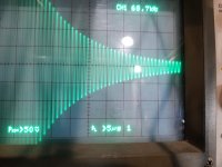
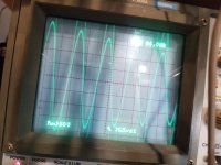
I am not really sure. With the setting you wanted me to measure it at it is very difficult to get a usable signal. The triggered light on my scope is randomly turning on and off while trying to take that measurement. I'm holding the probe on the shunt resistor and trying to get a better picture all while the power supply is screaming at me. While making adjustment on my scope I'm definetly seeing things I've never seen in the analog world. The best clear pics I seem to get are adjustments far from your recommendations. The first pic is at the shunt resistors and the second is from the output with a load.
Attachments
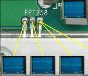
The attached file shows what I'd expect to see. The drain of the FET258 is directly connected to the shunt resistor.
Reduce the 12v supply voltage to just above the minimum where the amp will function to see if that will quiet the supply.
As a side note, this is still the analog world but it's switching so it's different than standard linear mode amplifiers.
Reduce the 12v supply voltage to just above the minimum where the amp will function to see if that will quiet the supply.
As a side note, this is still the analog world but it's switching so it's different than standard linear mode amplifiers.
Attachments

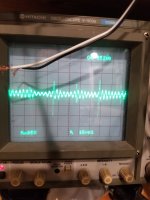
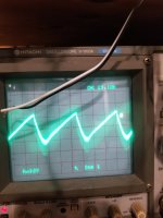
Regardless of what I do I cant get it to produce that square type wave that your expecting to see. I think whatever is wrong with it is why it wont.
Bringing the voltage down on my power supply from 13.5v to a little over 12v did help a bunch with the amps squealing ps.
Bringing the voltage down on my power supply from 13.5v to a little over 12v did help a bunch with the amps squealing ps.
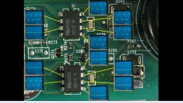
Setting the scope to 1v/div, look at both inputs of the two optocouplers. Do you see a clean ground (0v) on one input and a waveform of approximately ±1.2v on the other inputs (see attached)?
I don't know if the timebase is going to need to be the input frequency or the expected carrier frequency (150kHz, give or take).
Do you have a square wave generator that will go to at least 100kHz?
I don't know if the timebase is going to need to be the input frequency or the expected carrier frequency (150kHz, give or take).
Do you have a square wave generator that will go to at least 100kHz?
Attachments
I do have a function generator that is more than capable of producing that frequency. Sondoni have to inject a square wave or shouldnitnallready be there?
I've never had to do this but it should be safe.
Remove R219 and connect the signal generator to the pad of C230 that would have connected to R219. The generator is likely protected but make the connection through a resistor. 470 ohm should be OK.
Watch for excessive current draw and shut down if it occurs.
Drive a signal between 100k and 150k into the op-amps and look for the signals shown on the last image posted. Do you get what's posted and no excessive current draw?
Is this procedure to test the op amps or some circuit upstream? I did get a couple replacement octo couplers in my recent parts delivery.
This is to check the circuit from the optocouplers towards the speaker terminals.
Depending on what you find, there may be more questions of the circuit including the 5532.
Depending on what you find, there may be more questions of the circuit including the 5532.
So I have my square wave on 5 6 7 8 of the one octocoupler and obviously on pin 2 as that's where I'm feeding it into. Pin 5 6 7 and 8 of the other one it is really tough too see if I do. There seams to pe a ton of noise on my bench prolly due to the power supply and amp powered up. Before feeding the wave into c230 I probed for that -1 volt on pin 4 and 8 of the one octocoupler and it is not there. Some of these I touch with my scope probe and the display on my scope disappears. Even zooming out it's not there. I am super confused as to why that is happening. To me it just looks like there is way to much noise on the bench to really get accurate measurements. I have my signal generator output turned all the way down as I'm betting it should be a very small signal. I'm starting to think this amp is not a good introduction to class d as a project ahhah. Or my scope is just too old. Idk but I've seen some very strange things on this scope the last couple days that I've never seen on any scope in the past. Maybe my scope is just not accurate at small voltages but I'd be hard pressed to believe that.
Now if I probe around again, nothing has changed. I dont have my square wave on pin 5,6,7,8. It's a messy 400khz wave that is present with my sg on or off.
Are you driving the input of the two optocouplers to get the ±1.2 (or a bit more) drive on both optocouplers like you see on the image?
If your scope has a 20MHz band limit switch, enable it.
Use the short ground lead that clips to the end of your probe and ground it to the ground plane near the input to the optocouplers. If you want, you can solder a short wire to one of the grounded input terminals of the optocouplers and ground the short probe ground to that.
Those two should reduce the noise.
This is a bad first class D when there are strange problems. An amp that uses an HIP4080 would have been a better choice if there was a choice. Some people choose a 10k watt+ amp as a first class D and those can destroy many parts, even after thorough testing.
Last edited:
- Home
- General Interest
- Car Audio
- MTX 1501D repair help