I get this going in and this coming out. The resistor was knocking the signal down a little bit so I did have to slightly raise the gain of my sg but really no difference except it does change now when I turn sg on and off.
Attachments
Set your scope to DC coupling.
Recheck the input to both optocouplers and see if they match the image.
Recheck the input to both optocouplers and see if they match the image.
I need confirmation that you have the correct ±input voltage on pins 2 and 3 of both optocouplers.
I am driving them to the 1.2v square wave. That is right at the opamp with the amp powered up. I do have the 20mhz bandwidth limit. Il engage that and try getting that ground closer.
Is the trace aligned to the center reference line when there is no input to the scope?
If so, set it there.
Do you know how to use your scope in differential mode?
If so, set it there.
Do you know how to use your scope in differential mode?
On pin 2 of one coupler and pin 3 of the other I have my input 1.2v square wave. Pin 3 and pin 4 of the other I get this. This is back on ac coupling . Even though the funky wave on both looks about the same on ac or dc coupling. Ac or dc coupling does change my wave on the input signal dramatically (specially voltage)
Attachments
I'm not sure what you're trying to say.
Drive the SG to enough output to duplicate what you see in the posted image. Use DC coupling and the same scope settings shown. Until we get that drive, precisely the same, we can't go any farther. Use DC coupling.
Differential mode question?
Drive the SG to enough output to duplicate what you see in the posted image. Use DC coupling and the same scope settings shown. Until we get that drive, precisely the same, we can't go any farther. Use DC coupling.
Differential mode question?
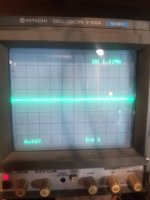
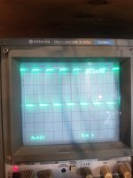
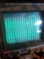
Ok. With the amp powered up and my signal in and the scope set to ac coupling. The first pic is my input and the second one is pin 5 on the one octocoupler that should match the input. It is a little messy but that depends on the sound the ps is making at that time. When it gets quieter the signal gets cleaner. If I hunt for on the scope for pin 5 signal I get this. So basically they far from match.
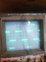
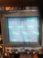
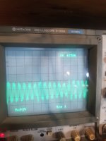
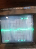
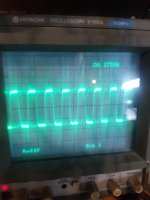
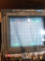
First picture= input signal pin 2 of op amp closer to center of board.
Second picture= when I probe pin 5 of same op amp.
Third picture= pin 5 of same op amp after adjusting x position to bring it into view.
First picture= input signal pin 2 of op amp closer to center of board.
Second picture= when I probe pin 5 of same op amp.
Third picture= pin 5 of same op amp after adjusting x position to bring it into view.
Attachments
Do you know how to use your scope in differential mode?
Is the op-amp that was shorted by the probe slipping, previously?
Do both optocouplers still have the 20-ish volts across pins 5 and 8?
Is the op-amp that was shorted by the probe slipping, previously?
Do both optocouplers still have the 20-ish volts across pins 5 and 8?
I do know how to use differential (thank you for helping me figure it out). This is not the same op amp I slipped the probe on.
The octocoupler I slipped the probe on has 20v, and the other one (signal pictured above) has 17.4.
The octocoupler I slipped the probe on has 20v, and the other one (signal pictured above) has 17.4.
Go to differential mode. Ch2 on pin 5. Ch1 on pin 6/7 (confirm that they are directly connected). DC coupling. 5v/div. Timebase to 5us.
Post the waveform for both optocouplers.
Post the waveform for both optocouplers.
I cant get a pic while holding both probes but there is no waveform. They cancel each other out allmost completely. Maybe .2v difference.
Last edited:
Both probes on each optocoupler. ch2 to pin 5 (this is like the ground probe for a multimeter), ch1 to pin 6/7 (equal to the red probe). Do this for each optocoupler.
Pin 2 on one and pin 3 on the other look to have about 1v, the other pins seem to have no voltage. So in differential mode I see a difference of about 1v. There is no waveform, it just looks like dc voltage on a scope, a flat line.
- Home
- General Interest
- Car Audio
- MTX 1501D repair help