In differential mode, post the waveform on one of the power supply FETs. Ch2 on terminal 3 of the FET. Ch1 on the gate (terminal 1).

If you get a signal there in differential mode, you should get one on the input to the optocouplers. Didn't you say that you got no signal there in differential mode?
I'm not sure what you're seeing with the two scope channels on pins 2 and 3. If necessary, solder a short wire (resistor leg?) onto one or both terminals and clip the probes to the wire(s) so that you can take a photo of the waveform.
The center conductor of the signal generator is connected to the terminal of C230 that's connected to R219. Connect the shield ground of the SG to the other terminal of C230 (actually ground). Make the connection to the pad on 230, not some other ground.
We need to get a good waveform confirmed across pins 2 and 3 in differential mode before we can be sure of anything else.
Last edited:
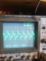
Understood. And yes I'm sure i have my sign wave at the octocouplers as you can see is post #264. I most likely need to adjust my scope to see it and I cant do that while holding the probes. I will solder some leads on them later so I can get a pic.
This is differential of pin 2 of one op amp and pin 3 of the other. I think last night I was thinking you were asking me for pin 2 and 3 on the same opamp wich would have gave me the 1.2v I was seeing. I did adjust the scope voltage division to get a better image.
Attachments
#264 is wrong because it's not swinging positive and negative.
The signal on pins 2 and 3 of the optocouplers should be a square wave, maybe not as slean as from the generator, but a square wave.
To see if the scope is showing the voltage correctly, set it to 5v/div, place the ch2 probe on the 12v PS ground terminal. The ch1 probe on the positive terminal. It should deflect approximately 2.2-2.5 (depends on actual supply output) divisions up. Is that what you get?
When I touch each probe independently to the 12v power supply they go to 12v (roughly 2.5 divisions) on scope. When I touch them both to 12v power supply the scope displays 0 volts.
My scope has a seperate ground that I have hooked to the negative terminal of the amplifier allready.
When you touch ch1, the trace should deflect up 2.5div. When you touch the ch2 probe to the positive terminal, the trace should deflect down 2.5div. Is ch2 going up?
Ya each one goes the opposite way until you touch both ar once and then they cancel each other out. Its definitely working like it should.
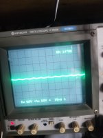
With the vertical amplifier set to 0.5v for both channels, do you still get the waveform in post 289?
What's the series resistor between the output of the generator and the board?
Is R219 out of the circuit?
What's the series resistor between the output of the generator and the board?
Is R219 out of the circuit?
Of course, in post 289 the scope was set to .5v for both channels.
The resistor between the board and sg is 470 ohms
R219 is out of the circuit.
The resistor between the board and sg is 470 ohms
R219 is out of the circuit.

Increase the generator output to increase the level at the optocouplers. That's not enough to drive them on.
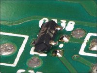
So before lifting this transistor I decided to wire a speaker up and make sure I still have the same issues (low garbled output). The speaker made a popping sound and the fuse blew in the amp. I unhooked the speaker and powered the amp back up. I checked the ouput and had 75vdc on it. I then shut off my signal generator and the dcv on the output is gone. Is this signal I'm feeding into the octocouplers my input or some kind of carrier or what?. I feel I should replace that resistor and remove my sg before lifting that transistor but wanted your input ahead of time.
- Home
- General Interest
- Car Audio
- MTX 1501D repair help