pinkmouse said:Quite possibly true, but a lot of kit doesn't have an electrical out these days.
That gear does not deserve a well designed DAC...
Really , there is no affordable substitute for SPDIF over coax that is better ( yet ). Todays optical interfacing for consumer devices certainly is not. In all cases I2S is the best way to go and build the DAC in the device whose data it will convert. What is the use for converting 24 bit 96 kHz data with a jittery interface ?
Maybe it is possible to provide some extra pads for mounting such a dreaded device instead of the BNC connector for those that want to go optical anyway ?!
EL Caps
So, I am thinking of using Elna RFS Audio Grade caps in the kits. Anyone have experience with them?
http://www.elna-america.com/products/pdf_files/AL/RFSe.pdf
All ELs are 10uF, I will be using the 35V version (overkill, but readily available).
[EDIT] Interesting translation in that datasheet... 😉
So, I am thinking of using Elna RFS Audio Grade caps in the kits. Anyone have experience with them?
http://www.elna-america.com/products/pdf_files/AL/RFSe.pdf
All ELs are 10uF, I will be using the 35V version (overkill, but readily available).
[EDIT] Interesting translation in that datasheet... 😉
Industrial low ESR electrolytics with a known good reputation are also a good choice in terms of price/performance. Some also sound equal or better but my experience with DIY dates from Silmic I. I've heard gear with Silmic II though and it sounded good. What about using Panasonic FC low ESR for decoupling the chips and using the Elna Silmic II caps in the signal path ?
For the signal path I would recommend either Wima MKS film caps with 5 mm pitch ( probably 4.7 or 6.8 uF 50V ) or Black Gate N series 10 uF 50V bipolar electrolytic caps if it have to be boutique parts. The latter sound very good but have a pricetag.
For the signal path I would recommend either Wima MKS film caps with 5 mm pitch ( probably 4.7 or 6.8 uF 50V ) or Black Gate N series 10 uF 50V bipolar electrolytic caps if it have to be boutique parts. The latter sound very good but have a pricetag.
Well, these are only $0.09 each, so not sure I would call them boutique (in price anyway). Another option would be the tried and true Panasonic FC...
BrianDonegan said:Well, these are only $0.09 each, so not sure I would call them boutique (in price anyway). Another option would be the tried and true Panasonic FC...
Did you read the datasheet ? 😉
No good source for Rubycon in the US. Could go through Farnell, but have to pay VAT and shipping.
I did read the datasheet. I actually thought it was kinda funny. But, I though people might like these more. BTW, I did say "price wise." 😉
I was actually hoping to use Panasonic FM (ultra-low imped), but they don't have a 10uF.
I did read the datasheet. I actually thought it was kinda funny. But, I though people might like these more. BTW, I did say "price wise." 😉
I was actually hoping to use Panasonic FM (ultra-low imped), but they don't have a 10uF.
Then stay with the Silmic II caps. They are quite inexpensive as I see now and they're good quality too. Do you want only one brand and type electrolytics in the kits ? Otherwise I'd still recommend using low ESR caps like Pana FC or FM for decoupling the Wolfson chip.
Brian wrote:
IMHO and IME Elna tend to sound warm and colorfull, with fat-round bass and a little limited highs (perhaps true?)
BG N is more neutral and with good HF extension and detail but also more expensive. I have them here 😎 and eventually will do a super-E cap essay, even if all audio-experts advice the contrary 😡
That said Rubycon is still a favorite (ZA for those sizes: 10uF/35V and 47uF/35V are both US$1.5 at http://www.referenceaudiomods.com/M...Screen=CTGY&Store_Code=RAM&Category_Code=RUBY )
I humbly apply as Beta tester:
Plan to--> CDPRO-2M->direct I2S->ALW superregulated 5V (3.3V worries me🙁 ) Opus DAC, balanced and DC coupled to-> transformer based volume control->balanced and DC coupled to Hypex UCD400-< Tannoy definition 500. minimalist approach.
Beware, I will consider my acceptance as beta tester as a lack of common sence from your part
Cheers,
M
Oh no! not again FC 😀Another option would be the tried and true Panasonic FC...
IMHO and IME Elna tend to sound warm and colorfull, with fat-round bass and a little limited highs (perhaps true?)
BG N is more neutral and with good HF extension and detail but also more expensive. I have them here 😎 and eventually will do a super-E cap essay, even if all audio-experts advice the contrary 😡
That said Rubycon is still a favorite (ZA for those sizes: 10uF/35V and 47uF/35V are both US$1.5 at http://www.referenceaudiomods.com/M...Screen=CTGY&Store_Code=RAM&Category_Code=RUBY )
I humbly apply as Beta tester:
Plan to--> CDPRO-2M->direct I2S->ALW superregulated 5V (3.3V worries me🙁 ) Opus DAC, balanced and DC coupled to-> transformer based volume control->balanced and DC coupled to Hypex UCD400-< Tannoy definition 500.
minimalist approach.Beware, I will consider my acceptance as beta tester as a lack of common sence from your part
Cheers,
M
No worries, to do I2S in (at 5V) simply omit all the receiver related parts including the input trafo and all its associated parts. The Wolfson chip has no problem with 5V digital inputs.maxlorenz said:I humbly apply as Beta tester:
Plan to--> CDPRO-2M->direct I2S->ALW superregulated 5V (3.3V worries me🙁 )
Cheers,
M [/B]
Cheers!
Russ
Hi Russ,
I may have been not precise in my post: I meant 5V and 3.3V power supplies. I don't know how high is my I2S digital out.
Yes, I can save a lot of parts 😉
Cheers,
M
I may have been not precise in my post: I meant 5V and 3.3V power supplies. I don't know how high is my I2S digital out.
Yes, I can save a lot of parts 😉
Cheers,
M
maxlorenz said:Hi Russ,
I may have been not precise in my post: I meant 5V and 3.3V power supplies. I don't know how high is my I2S digital out.
Yes, I can save a lot of parts 😉
Cheers,
M
I am saying if you omit the receiver you will only need 5V. You would probably want two though.
Rather than just grounding the extra receiver inputs, why not run 1 or 2 of them to a solder pad at the board edge? It would make the boards even more flexible.
-David
-David
dw8083 said:Rather than just grounding the extra receiver inputs, why not run 1 or 2 of them to a solder pad at the board edge? It would make the boards even more flexible.
-David
It is possible, but then I would also have to add two more jumper headers so you could install switches/jumpers to select the input. I am not sure I have room for that. I will check into it. 🙂
:EDIT: I would also have to directly AC couple RXN to GND. I am not sure is that is desirable. You could not as easily do balanced serial input.
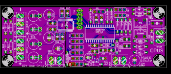
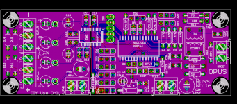
Progress report.
I really appreciate the thoughtful input and support provided so far. There are a lot of hours of development in this thing. I am sure many are learning a lot. I know I am! 😀
Beta testers you are putting a lot of faith in me and this circuit. I really do not want to let you guys down. I have no idea if it will work correctly or not since I have no other way to test it but to get these boards made. So thanks for the votes of confidence, but if you are not willing to take that risk, then please just wait for us guinea pigs to finish our work. 😀.
The best way to get success if for many eyes to look at the circuit. I am especially concerned if I am handling the following correctly.
1) Serial data rates (what if I have 48khz signal and then 192khz signal). Will I need to adjust the filter on the receiver?
2) Serial input (though I am feeling much better about it now).
3) Resets. The way I read the data sheet, the only truly necessary reset is on power up, so I think I have it right. I reset both devices at startup.
4) Master/Slave mode. This one still has me a bit puzzled.
To insure interested parties have enough time to review the circuit, I will not order the PCBs until Monday. Please, please, please take the opportunity to review things over the weekend. I will be checking email often until then.
Cheers!
Russ
- Home
- More Vendors...
- Twisted Pear
- Mr White's "Opus", designing a simple balanced DAC