Re: One last question
I am looking at you pics, are you till having issues?
Anywhere from +/-12V to +/-15V is fine. 🙂
I personally use +/- 15V as the distortion goes down as the voltage goes up.
Cheers!
Russ
Nortp said:What voltage do you recommend that the LCBPS be set for ?
Thanks,
PJN
I am looking at you pics, are you till having issues?
Anywhere from +/-12V to +/-15V is fine. 🙂
I personally use +/- 15V as the distortion goes down as the voltage goes up.
Cheers!
Russ
Yes still having issues
Hi Russ,
Nothing has changed, I looked carefully at the pic of the completed LCBPS that Brian had posted a while back and I'm think that that I assembled it correctly, and hooked up the trafo correctly. The higher voltage DC seems consistant with what you'd expect after rectification, but adjusting the pots has no effect. Do you thing that the pots might be bad ? Both bad seems like a long shot, me screwing something up has better odds.
PJN
Re: Yes still having issues
I think its time to start checking for shorts etc. I can't really see anything obviously wrong in the pics.
Nortp said:Hi Russ,
Nothing has changed, I looked carefully at the pic of the completed LCBPS that Brian had posted a while back and I'm think that that I assembled it correctly, and hooked up the trafo correctly. The higher voltage DC seems consistant with what you'd expect after rectification, but adjusting the pots has no effect. Do you thing that the pots might be bad ? Both bad seems like a long shot, me screwing something up has better odds.
PJN
I think its time to start checking for shorts etc. I can't really see anything obviously wrong in the pics.
Just for fun
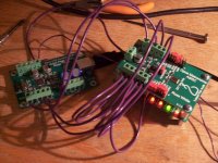
I wanted to test all of the feature of a couple of our modules. So I rigged up the following.
USB module ---> Metronome(ASRC) ---> Transceiver (WM8804)
I took just BCK/LRCK/DATA from the USB module simulating a CDPro or similar situation and ran it int the Metronome. SCK is an output on that board anyway so you would not connect it in any case.
Then I took the I2S out (including master clock) from the Metronome into the WM8804 transceiver module. The metronome is setup to re-clock at 96/24 with a 256fs master clock.
I set the transceiver module to be in AIF slave mode (AIF clocks become inputs). And used the SPDIF output of the transceiver. This goes out to another dac. Well it works very well. 🙂 And even sounds very nice!
Now in the pic you will notice the SPDIF input flag lights are red and non-audio LED is green, thats ok because there is no SPIDF input, just output.
Cheers!
Russ
Attachments
Ok
Ok, I'll check the board out carefully with a magnifier and reflow all the joints and report back.
PJN
Ok, I'll check the board out carefully with a magnifier and reflow all the joints and report back.
PJN
LCBPS status for BALSIE
Russ/Brian,
I reflowed all the joints and checked for shorts, found none. I was able to get the pots to lower the DC output voltage to 17.6 VDC. Turning the screws would not lower it anymore. Is 17.6 VDC safe for the BALSIE, or will it cause performance issues ? Funny thing is that my meter measures 17.5 VAC on both the Trafo's, that seems like a bit out of tolerance, I wonder if my multimeter is off.
PJN
Re: LCBPS status for BALSIE
Thats a bit on the high side if your DMM is correct. I would not try it.
Check your DMM against a known voltage. Is it reading sane numbers for the other PS?
Nortp said:Russ/Brian,
I reflowed all the joints and checked for shorts, found none. I was able to get the pots to lower the DC output voltage to 17.6 VDC. Turning the screws would not lower it anymore. Is 17.6 VDC safe for the BALSIE, or will it cause performance issues ? Funny thing is that my meter measures 17.5 VAC on both the Trafo's, that seems like a bit out of tolerance, I wonder if my multimeter is off.
PJN
Thats a bit on the high side if your DMM is correct. I would not try it.
Check your DMM against a known voltage. Is it reading sane numbers for the other PS?
BrianDonegan said:Ordered crystals and SRC chips this morning. We have 23 boards on hand.
Ohh, gimme gimme gimme 🙂 Who do I have to fondle to get one?
Re: LCBPS status for BALSIE
Try checking out the resistances around the LM317 i.e that the 240 ohm resistor is indeed 240 ohms, and that the potentiometer is of the correct value and varying it's value as it should when turned. Also check that your diodes are correctly oriented.
Nortp said:Russ/Brian,
I reflowed all the joints and checked for shorts, found none. I was able to get the pots to lower the DC output voltage to 17.6 VDC. Turning the screws would not lower it anymore. Is 17.6 VDC safe for the BALSIE, or will it cause performance issues ? Funny thing is that my meter measures 17.5 VAC on both the Trafo's, that seems like a bit out of tolerance, I wonder if my multimeter is off.
PJN
Try checking out the resistances around the LM317 i.e that the 240 ohm resistor is indeed 240 ohms, and that the potentiometer is of the correct value and varying it's value as it should when turned. Also check that your diodes are correctly oriented.
Metronome Available
Hi Folks,
I ordered enough extra boards of the Metronome prototype to offer a few modules to you folks who might want one. Brian has been kind enough to offer to build some up and we will go ahead an offer them until we run out. At some point I will order more, but this first batch is small.
The XO is a 24.576mhz extremely low jitter crystek part which is perfect for doing 96/24(256fs) or 192/24(128fs).
There is an order link up on the Opus order page.
I don't have a manual done up yet, but I can post pics for anyone who needs to know how to set it up. It's not very difficult.
Cheers!
Russ
Re: Having issues with LCBPS for Balsie
I have the same problem. Although I seem to have a slightly different LDBPS, I can only get the ouput voltages down to 19.7v and 18.6v. Can't get them down any lower. Also Resistors R1-R2 seem to get hot as do the heatsinks, although this could be normal? Input voltages in from the transformer seem to be OK at 17.6-18.0v. Having also just built the PS for the DAC I'm a bit confused as that is working very well.
Anyone any ideas?
Nortp said:....the LDBPS for the balsie doesn't seem to be resopnding to the pot adjustments. On the tranfo inputs I'm reading 17.2 VAC across the blk & red, and across the yellow & orange feeds to the PS. On the LCBPS outlets I'm reading -20.6 VDC and 21.3 VDC between the gnd and - & + terminals. Adjusting the pots does nothing at all. I've included some pics of the hookups. What do you think I'm doing wrong?...
I have the same problem. Although I seem to have a slightly different LDBPS, I can only get the ouput voltages down to 19.7v and 18.6v. Can't get them down any lower. Also Resistors R1-R2 seem to get hot as do the heatsinks, although this could be normal? Input voltages in from the transformer seem to be OK at 17.6-18.0v. Having also just built the PS for the DAC I'm a bit confused as that is working very well.
Anyone any ideas?
Re: Re: Having issues with LCBPS for Balsie
Check resistor values, it is possible one is incorrect.
Also diode orientation and such as mentioned earlier. Also be sure there are no shorts. Use your DMM and measure resistance across caps if it is 0 or close to 0 then there is a short some place.
Cheers!
Russ
rjbaldwin said:
I have the same problem. Although I seem to have a slightly different LDBPS, I can only get the ouput voltages down to 19.7v and 18.6v. Can't get them down any lower. Also Resistors R1-R2 seem to get hot as do the heatsinks, although this could be normal? Input voltages in from the transformer seem to be OK at 17.6-18.0v. Having also just built the PS for the DAC I'm a bit confused as that is working very well.
Anyone any ideas?
Check resistor values, it is possible one is incorrect.
Also diode orientation and such as mentioned earlier. Also be sure there are no shorts. Use your DMM and measure resistance across caps if it is 0 or close to 0 then there is a short some place.
Cheers!
Russ
Re: Metronome Available
Very cool - order placed. I have a couple ideas for this one.
Of course, I haven't even assembled my Opus yet, so I'm probably jumping the gun a bit......
Russ White said:Hi Folks,
There is an order link up on the Opus order page.
Cheers!
Russ
Very cool - order placed. I have a couple ideas for this one.
Of course, I haven't even assembled my Opus yet, so I'm probably jumping the gun a bit......
LSBPS issues update
Well I triple checked the diode orientation it is correct according to the schematic and the tracings on the board itself.
I checked all of the resistors R 1,2,3,4 are 10 ohm, R5&6 near the IC are 240 ohm.
I checked the variable pots, the orientation is correct as indicated on the board tracings, the resistance between the center pole and the one by the adj screw is 0 ohms. Adjusting the screw does give variable resistance between the center pole and the pole opposite the adj screw, and between the pole by the adj screw and the pole opposite.
I also checked all of the caps for shorts and found none
I still can't adjust the DC below 17.6 and 16.5 ohms respectively.
At this point I am at a loss as to what to do next, any suggestions would be greatly appreciated.
- Home
- More Vendors...
- Twisted Pear
- Mr White's "Opus", designing a simple balanced DAC