Russ White said:Opus works just fine into any balanced load > 1K. Absolutely nothing is "required" for good results. In fact I would say that it is ideal to use it this way if you can. 23K would be a very very easy load.
Cheers!
Russ
So, if I'm going to build an opus with the ballsie(for SE output),
And I'm going to use the balanced out only with high impedance amp(Beta22 headphone amp) it will be better to connect the the balanced outputs directly to the opus boards?
SoapSeller said:
So, if I'm going to build an opus with the ballsie(for SE output),
And I'm going to use the balanced out only with high impedance amp(Beta22 headphone amp) it will be better to connect the the balanced outputs directly to the opus boards?
Thats what I would do, yes.
But you could also use the balanced out from the Ballsie. Try both and see which you like better.
Cheers!
Russ
Great, I will try them both 🙂
If I understand correct, I can also safely try to bypass the opus output caps, right?
If I understand correct, I can also safely try to bypass the opus output caps, right?
Hello,
@Russ White: you are finished to test the sound type of Opus DAC
I am very interesting on your DAC and Preamp module kit
Thank you
@Russ White: you are finished to test the sound type of Opus DAC
I am very interesting on your DAC and Preamp module kit
Thank you
Opus sound
Hi Russ (opus team)
I to would be very interested in your thoughts on the sound and perhaps some comparisons to some of the established dacs available commercially. I do know that this is a very subjective request however I am sure that with your experience you would be able to describe the overall performance that no doubt keeps you active in developing the opus.
I look forward to your thought as I am sure many would be.
Thank you for your time
While waiting for Russ and Brian's Metronome ASRC, I decided to try fitting my own ASRC between Wolson receiver and DAC. The chip used is an AD1896 left over from a previous project. I've used a Tent Labs 24.576MHz (96KHz sample rate) oscillator fed from a Pink Flea reg.
I won't say a lot about the sound, except that it adds to transparency. If you like your Opus, you will like it more with a Metronome!
Dan
I won't say a lot about the sound, except that it adds to transparency. If you like your Opus, you will like it more with a Metronome!
Dan
Russ, Brian
My modules arrived today! 🙂
Very well packed and the soldering job on the PCB's is truly amazing. I hope to quickly find some time to assemble all those boards together and enjoy the sound they will produce.
Regards
My modules arrived today! 🙂
Very well packed and the soldering job on the PCB's is truly amazing. I hope to quickly find some time to assemble all those boards together and enjoy the sound they will produce.
Regards
DarrenWadsworth said:
How about something more challenging?
🙂
Sorry about the noob question.
It looks like that switch selects either spdif or USB for input, and turns off the unit.
I take it that the input modules (usb,spdif) ouputs are connected to the switch. And somehow power is connected.
I would like to control my DAC in the fashion as I will need to use those inputs.
However, I do not know how. If you have the time, I would GREATLY appreciate either a connection diagram or just text explaining what goes where. All of the other connections etc, I have worked out. Just not how to switch the 2 inputs and power(which I could use a seperate switch but this is neater).
Thank you
Darren
I never got any help with this. Please...
🙂
I received the caps for the ballsie yesterday and put them in, let it cook overnight. Just wanted to say that it sounds really great. Thanks Brian and Russ.
DarrenWadsworth said:
I never got any help with this. Please...
🙂
We did this with a custom little relay PCB, but you could also use switch or two.
I actually don't know enough about he guts of how Brian did it to tell you much more. 🙂
Cheers!
Russ
Now for something a little fishy.. 🙂
Some of you may be interested in this:
http://www.diyaudio.com/forums/showthread.php?s=&threadid=111863
Cheers!
Russ
Some of you may be interested in this:
http://www.diyaudio.com/forums/showthread.php?s=&threadid=111863
Cheers!
Russ
Thank you Russ and Brian, my Opus went together easily!
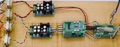
Line up- Mac G5 usb to i2s>Opus dual mono>ballsie>rebuilt Grundig PPEL84 amp>Optimus LX4 speakers....my little computer listening system.
First impressions- Wow. Great imaging. Smooth, but articulate. Clean. Bass? Yes it’s there, just not the flubbery loose kind. When it's raising the hair on the back of my neck- it’s got to be good!
Admittedly, I am comparing to the computer's dac. I cant wait to get it on my main system!
I can't stop listening to my music!😀 Darn, you! I've got to get work done!
My pic- quickey breadboard set up. The opus differential outputs were hardwired underneath, thus only 3 wires seen from opus to ballsie.
I plan to hardwire most of the boards together in the final form.
Thanks again for such a great kit!😀
-Kent
Attachments
Excellent work! 🙂
That photo will make a nice reference for other builders.
I am very glad you have found the project enjoyable. I have been having a lot of fun with it too. 🙂
Cheers!
Russ
That photo will make a nice reference for other builders.
I am very glad you have found the project enjoyable. I have been having a lot of fun with it too. 🙂
Cheers!
Russ
Kent,
it might be worth experimenting with bypassing the filtering resistors in the ballsie's power supply. I suspect doing so will improve bass/dynamics.
Yeah, the Opus is great fun, whether building to the original recipe or as a base for experimentation.
Dan
it might be worth experimenting with bypassing the filtering resistors in the ballsie's power supply. I suspect doing so will improve bass/dynamics.
Yeah, the Opus is great fun, whether building to the original recipe or as a base for experimentation.
Dan
Spartacus said:it might be worth experimenting with bypassing the filtering resistors in the ballsie's power supply. I suspect doing so will improve bass/dynamics.
While that might be fun to try, I actually doubt it will actually have much effect. Though it probably won't hurt much either 🙂 Noise wise, it is likely to be worse.
And actually there are two version of the split rail PS, you may be referring to the older one, the newer one has a common mode choke in addition the the CRC of the old one. Bypassing the resistor(with a cap) with the choke in place will effect the filter, and not for the better unfortunately.
Kent has the newer one with the choke.
Cheers!
Russ
Hi Russ,
I'm suggesting to link out the resistor and inductor entirely, in order to reduce the impedance of the supply. As you say though, noise rejection will be less. Swings and roundabouts!
It may not do any good at all of course, but it's a free and quick experiment. My experience is that anything you can do to lower supply impedance will help with dynamics/bass.
Dan
Spartacus said:Hi Russ,
I'm suggesting to link out the resistor and inductor entirely, in order to reduce the impedance of the supply. As you say though, noise rejection will be less. Swings and roundabouts!
Dan
It actually would not reduce the impedance of the supply as that is dictated by the impedance of the caps after the filter and the operation of the VREG itself. 🙂 This is actually very easy to test both in theory and in practice.
Basically all that change would it would do is allow more input noise through to the ballsie.
🙂
As long as the input voltage is high enough to allow for 3-4V drop into the VREG, the output of the supply will be dominated by the caps directly preceding the VREGs. 🙂 This is why they are on the largish side and are very low ESR.
Cheers!
Russ
Russ White said:
It actually would not reduce the impedance of the supply as that is dictated by the impedance of the caps after the filter and the operation of the VREG itself. 🙂 This is actually very easy to test both in theory and in practice.
While theory might suggest the above, my practive, and that of many others, indicates that impedance prior to a reg i.e. resevoir caps/transformer etc. does have a significant impact.
With a chip such as the LM4562 which already has excellent PSRR in unity gain it may not matter much.
I'll try to dig up some information on this .......
Cheers,
Dan
Spartacus said:
While theory might suggest the above, my practive, and that of many others, indicates that impedance prior to a reg i.e. resevoir caps/transformer etc. does have a significant impact.
With a chip such as the LM4562 which already has excellent PSRR in unity gain it may not matter much.
I'll try to dig up some information on this .......
Cheers,
Dan
And don't forget the the PSRR and output impedance of the VREG itself.... And then there are caps after the VREG. 😉
Honestly, in then end, it is all good fun, so do what makes it enjoyable for you.
Still the design choices were made to limit noise as much as possible in a small space while still maintaining output impedance which is actually lower than the impedance of the transformer you are drawing your power from 😉. You gotta love feedback.
Cheers!
Russ
Russ,
When feeding the Opus DAC with a "Low Current Dual Power Supply", am I right that a transformer with dual 0-9V secondaries is sufficient enough. The LCDPS needs to be set at 5V and 7,5V so I don't see a point of using a transformer with 15V secondaries. With 9V (x1.412) the voltage regulators will run a lot cooler I guess.
Regards
- Home
- More Vendors...
- Twisted Pear
- Mr White's "Opus", designing a simple balanced DAC