Not as far as I know, but if you suspect that kind of problem, try it at a lower voltage using your Variac to adjust the line voltage.Hi Pete,
I have assembled a new CP using the parts you listed below except I used MUR860G for the diodes. For some reason, I can't seem to get it to adjust the voltage. Are there some resistor changes that need to be made as well?
Thanks, Terry
Is this still a go?
I'm interested in a couple as well if their available.
Thanks
Hallo Peter and all other DIY'er
I'm also interested to order and buy a 2 Set of Boards to finnish my SonnyA TSSA Amps.
There avaiable plaese some Info.
To all best Regards to lucky Start up to 2014.
Thanks.
I'm also interested to order and buy a 2 Set of Boards to finnish my SonnyA TSSA Amps.
There avaiable plaese some Info.
To all best Regards to lucky Start up to 2014.
Thanks.
I would like to order 2 boards if there are some available
Gesendet von meinem SGPT12 mit Tapatalk 2
Gesendet von meinem SGPT12 mit Tapatalk 2
Terry,
Did you ever get this figured out.? i have 2 CP that won't adj. either although i used all orig. parts except 15K caps for C1 & C2.
"I have assembled a new CP using the parts you listed below except I used MUR860G for the diodes. For some reason, I can't seem to get it to adjust the voltage. Are there some resistor changes that need to be made as well?"
Yes. The problem was that I used KSC1845/KSA992 for the BJT's. They have and ECB pinout. The boards are designed for BC550/BC560 so the pinout is CBE. I swapped those out and it is working perfectly.
Yes. The problem was that I used KSC1845/KSA992 for the BJT's. They have and ECB pinout. The boards are designed for BC550/BC560 so the pinout is CBE. I swapped those out and it is working perfectly.
AH,
Well, guess i need to do some more investigating then. 😕
Nothing obvious yet.
AH,
Well, guess i need to do some more investigating then. 😕
Nothing obvious yet.
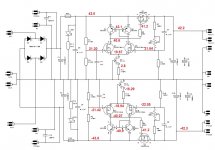
What rail voltage are you running. I could probably post a schematic with voltages at each transistor if that would help you.
Blessings, Terry
Terry,
Thank You, that would be a big help. 😀
I am running +- 43.7 at the fuse.The first 3 i built came up & adj. with no load. This last one & my etched version of his Single Layer won't adj.
Thank You, that would be a big help. 😀
I am running +- 43.7 at the fuse.The first 3 i built came up & adj. with no load. This last one & my etched version of his Single Layer won't adj.
Terry,
Thank You, that would be a big help. 😀
I am running +- 43.7 at the fuse.The first 3 i built came up & adj. with no load. This last one & my etched version of his Single Layer won't adj.
Hi Rick,
Here is a schematic with the voltages I read with the PSU set to +-43.6 at the fuses and the output set to approximately +-43.2 with no load on it. Hope this helps.
Attachments
- Home
- Group Buys
- Mr Evil's Capacitance Multiplier Power Supply PCB