Here are the measurements of the JG Filter-Buffer.
The maesurements are done at 4V P-P.
The first measurement is done with the coil jumpered. I wanted to find out if the coil adds distortion. That is obviuosly not the case at this level the second measurement shows where i measured the other channel that has the coil in the signal chain.
This buffer has another character then the B1, less second, more third.
On the other hand reducing the 4V P-P by 3dB ( third picture ) the distortion is so low that i reach my maesureemnt limit. It is cetainly of a monotonic character.
Curious why the strange fundamental frequency (1.45kHz)?
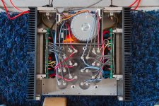
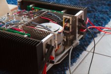
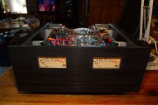
Here a few pictures, to show that the amplifier truly exists 🙂 also the new laboratory now equipped with ESD floor and workbench.
Attachments
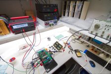
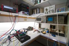
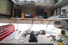
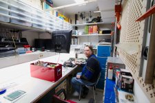
Here a few pictures, to show that the amplifier truly exists 🙂 also the new laboratory now equipped with ESD floor and workbench.
Envious of your lab Frans...so clean and tidy! Also very impressed with your amplifier design. Can you explain the grounding arrangement of the large filter caps? It looks somewhat unconventional.
Envious of your lab Frans...so clean and tidy! Also very impressed with your amplifier design. Can you explain the grounding arrangement of the large filter caps? It looks somewhat unconventional.
There are 3 star's +70, -70 and ground, these star's are on the board, and that is where the capacitors connect (and every thing else). This thing is unconventional 🙂 and designed to be unconventional.
There are 3 star's +70, -70 and ground, these star's are on the board, and that is where the capacitors connect (and every thing else). This thing is unconventional 🙂 and designed to be unconventional.
I'm curious if connecting that first filter cap in each case via bus bars to the others would result in a reduction in rectification (100/120Hz) noise. Usually I have found that directly connecting those "noisy" nodes from the rectifier to the stars is a bad idea. I'll be following your progress closely! 🙂
Last edited:
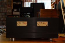
Very nice lab space, very cool builds. Those VU beg for tear down and FDW in deville font printed on their clean space. FG to 0.5MHZ only? 0.005% THD alright but some faster pulse edge would be needed in the future...
When finished the front panel will be in line with this All sizes | RIAA Preamplifier | Flickr - Photo Sharing! the cover and back panel will be perforated steal, this steal will be, chrome, copper, bronze or yellow-copper plated 🙂, you have to remember, this is 'only' the proto type 🙂
Very nice lab space, very cool builds. Those VU beg for tear down and FDW in deville font printed on their clean space. FG to 0.5MHZ only? 0.005% THD alright but some faster pulse edge would be needed in the future...
The imprinted text will (most probably) be this:
Signature Transresistance Current-Feedback BIGBT Amplifier - Frans de Wit
With thanks to 'Lazy Cat' 🙂 (also note that this is not a SSA or comparable design)
Last edited:
You're using LazyCat's balanced compound blocks ?
Been counting the power device pairs under the board, but still fail to spot any ménage-à-trois business going on.
Not using fancy emitter resistors, are you ?
Been counting the power device pairs under the board, but still fail to spot any ménage-à-trois business going on.
Not using fancy emitter resistors, are you ?
Cool Frans, the amp looks good.
I like the "flying" screen in your lab.
I have seen part of the circuitry of Frans amp and it is innovative.
The main issue is ( was ? ) to stabilize it because it is a VFA with a CFB "flavour" .
When Frans broke the loop on the simulator i could have sworn that the input stage is VFB and the output stage CFB.
That 1.45kHz does not have a particular reason. I could have taken 1kHz. More taxing would be a double tone, say 19kHz plus 20kHz.
You're using LazyCat's balanced compound blocks ?
Been counting the power device pairs under the board, but still fail to spot any ménage-à-trois business going on.
Not using fancy emitter resistors, are you ?
This one is a 'manage-à-cenq' 🙂
Cool Frans, the amp looks good.
I like the "flying" screen in your lab.
You have to find your driving boots, this thing is singing like a thousand-and-one Nightingales.
This one is a 'manage-à-cenq' 🙂
Naughty boy, using such expensive RTO's.
(if you make this one public, some may be challenged to use €50 each VFP-4 )
Naughty boy, using such expensive RTO's.
(if you make this one public, some may be challenged to use €50 each VFP-4 )
What RTO do you mean RTO - What does RTO stand for? Acronyms and abbreviations by the Free Online Dictionary.
Sfernice RTO-20 (the 0R5/20W)
Board looks difficult to mount, with 8 power devices on one side, and 8 emitter resistors on the other side of the aluminum blocks.
(lange imbus-sleutel, zeker ? )
)
Board looks difficult to mount, with 8 power devices on one side, and 8 emitter resistors on the other side of the aluminum blocks.
(lange imbus-sleutel, zeker ?
)
Last edited: