The energy in R15, R16 is simply dumped to ground. That´s when i say "Who has, has".
It may have an effect on the distortion spectrum though that is positive.
It may have an effect on the distortion spectrum though that is positive.
One way to degenerate the second stage is to insert a "magic resistor" between the Fets and the Bipolars.
One way to degenerate the second stage is to insert a "magic resistor" between the Fets and the Bipolars.
You mean by adding a resistor between gate of J3 and collector of Q3 (and same for the other halve)?
If that is what you meant to say, I tried it that and works really well nevertheless there is a significant power dissipation there as feedback resistor's value goes down.
Joachim,
I tried to simulate the circuit you posted a couple of pages ago (the vendetta type).
Nevertheless, the simulator shows that the servo's circuit is not working which makes me think at this point that there is something wrong with my model.
Maybe the spice model I have for the J74 and K170 are not correct and are causing these issue with the Servo.
Could you or anybody here post the a valid model that has been used with success for the K170 and J74?
For simplicity I am attaching my simulation file for reference.
Thanks everybody.
Attachments
Joachim,
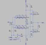
I am still working on simulation for servo gain stage and buffer.
Does the servo look good?
In this case it is not on the signal path, but I am not sure it could work in practive.
It simulates just fine and with an input offset it acts and zeros the output out.
Would you mind comment it?
Thanks,
The offset is almost not influenced by the current in the current mirrors, try the simulation below. To correct an offset of 12mV a current offset of 500uA is needed. The current source is not the place to use (to control the offset).
Attachments
I see what you are saying.
Where would you then control the offset otherwise?
Also, why not even the simulation for the vendetta's offset control seems to properly work when in the reality that is a proven circuit?
Where would you then control the offset otherwise?
Also, why not even the simulation for the vendetta's offset control seems to properly work when in the reality that is a proven circuit?
I see what you are saying.
Where would you then control the offset otherwise?
Also, why not even the simulation for the vendetta's offset control seems to properly work when in the reality that is a proven circuit?
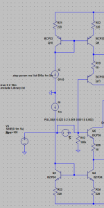
One way to find that out is to use the simulator, use the ".step param x list ..." command and inject currents/voltages at different points. Find the spot where the 'injections' have the largest influence and you are near a solution (also you will gain some deeper understanding of the circuit).
Joachim,
I tried to simulate the circuit you posted a couple of pages ago (the vendetta type).
Nevertheless, the simulator shows that the servo's circuit is not working which makes me think at this point that there is something wrong with my model.
Maybe the spice model I have for the J74 and K170 are not correct and are causing these issue with the Servo.
Could you or anybody here post the a valid model that has been used with success for the K170 and J74?
For simplicity I am attaching my simulation file for reference.
Thanks everybody.
Hi Stefanoo,
in your schematic, the servo is only influencing the upper half, so if the offset falls into the other quadrant it cannot influence it. you could try connecting it to the input for testing, or to the midpoint of R7 and see what happens...
just my two cents
78 sets and counting..... its getting quite a lot now. I will be looking into new quotes to eventually get the cost down.
Joachim, your phono stage is very popular!! (As it should be, given its quality)
Joachim, your phono stage is very popular!! (As it should be, given its quality)
I wonder how it will compete against my XOno. 🙂
What is actually the input voltage the reguator want's to see? Probabely I can recycle my XOno PSU for that.
What is actually the input voltage the reguator want's to see? Probabely I can recycle my XOno PSU for that.
Last edited:
I wonder how it will compete against my XOno. 🙂
What is actually the input voltage the reguator want's to see? Probabely I can recycle my XOno PSU for that.
A minimum of 30VDC, more would be better with a maximum of 42VDC.
See 6.1 in http://en.wikipedia.org/wiki/42_(number)
Ooops my mistake, that was for the Pradise 1, for the Paradise 2 (running at 18V) it should be 24VDC minimum up to 35VDC maximum. For best performance an reasonabel disipation I would select 29VDC that is a 22VAC transformer, transformers from 20VAC up to 25VAC can be used.
Last edited:
A minimum of 30VDC, more would be better with a maximum of 42VDC.
See 6.1 in http://en.wikipedia.org/wiki/42_(number)
Are you talking about the new Paradise working at 18V ?
Using 42Vin would create a 16Vdiff Vin-Vout this would need to be dissipated in heat right ?
Are you talking about the new Paradise working at 18V ?
Using 42Vin would create a 16Vdiff Vin-Vout this would need to be dissipated in heat right ?
Ooops my mistake, that was for the Pradise 1, for the Paradise 2 (running at 18V) it should be 24VDC minimum up to 30VDC maximum.
At what point the cascoded CFP bootstrap CCS drops out? 1.4V > Vo break point? So people could know limits VS mains tolerances and trafos.
Hm... XOno PSU has 30VAC. This is to much.
As I have a Nagrad UPS in the pipe, I am going to use this. This does the trick, I think. 😉
That will be a blast! 😀
As I have a Nagrad UPS in the pipe, I am going to use this. This does the trick, I think. 😉
That will be a blast! 😀
At what point the cascoded CFP bootstrap CCS drops out? 1.4V > Vo break point? So people could know limits VS mains tolerances and trafos.
The CCS uses one Led as an reference and the CVS that feeds the CCS uses two Led's as an reference, that makes that optimum regulation is lost when the CVS looses it's headroom. If you give the CVS 2Vols headroom, then the minimum DC-in would be "DC-out + (2 * Led) + 2Volts headroom" = "18 + (2 * 1.7) + 2" = 23.2 to this we have to add the 'ripple-floor' of the raw-input-voltage (lets say 1Volt) and we get at "23.2 + 1" = 24.2Volts minimum input voltage (when using 1.7Volts drop on the Led).
Also having a load of BF245C will they be acceptable to sub J310 as the error amp's active load in the reg and in other places in the phono maybe? They would need some Irish dancer feet bend but they pay in noise figure.
The CCS uses one Led as an reference and the CVS that feeds the CCS uses two Led's as an reference
Right. I thought they were mere diodes until I zoomed in the PDF.