Perfect... I have lots of those
This new paradise r2 works at 18v... so considering shunt vin vout I should feed something like +-28V raw DC right ?
This new paradise r2 works at 18v... so considering shunt vin vout I should feed something like +-28V raw DC right ?
Last edited:
Perfect... I have lots of those
This new paradise r2 works at 18v... so considering shunt vin vout I should feed something like +-28V raw DC right ?
Yes.
BTW I'm sory to hear about the R1 transistor replacement failing? Did you you first cut the legs and than remove them one by one, or did you try to remove the transistor in one go?
I know that but it seems the legs have been cut before.... it was not good already.
To repair it I must remove the heat sink and redo the pads with external wires... I do not think it is worth the effort becuse in the end, the trouble might not be confined to the shunt as it was producing the correct +-24v... I always had trouble with this channel.... the other one worked from day one but not this one.
I will forget it for a while and build the paradise r2 now
I know that but it seems the legs have been cut before.... it was not good already.
To repair it I must remove the heat sink and redo the pads with external wires... I do not think it is worth the effort becuse in the end, the trouble might not be confined to the shunt as it was producing the correct +-24v... I always had trouble with this channel.... the other one worked from day one but not this one.
I will forget it for a while and build the paradise r2 now
One thing more about removing stuff from a board; do use a temp controlled soldering iron! Other irons will get to hot and damage the board. (Just posted for general interest 🙂)
Today I removed the heatsink... not a big deal after all 🙂
But now I found that hesener did change radically the negative shunt .... I did not know that and my attempt to get the correct voltages might have been very wrong.
Must speak with him to understand the mods.
But now I found that hesener did change radically the negative shunt .... I did not know that and my attempt to get the correct voltages might have been very wrong.
Must speak with him to understand the mods.
I am sorry that the first Paradise version gives such trouble. They work in Heseners setup but as soon as they have left the creator they have a life of their own.
The new version does not present problems so far.
I have a little project where i plan to use the ATL Mini Shunts. I found two little bugs :
First : the BD transistors have to be turned 180 °
Second : I set the ouput voltage with two 12V Zeners and supply the Shunts with my Nobrainer Preregulator. I put on dummy resistors to simulate a load of 20mA.
Under this condition i get plus 11.4V and minus 11.7V. I then measured the voltage over the Zeners and that was quite different. This behaviour is not critical when we supply integrated Opamps. They can stand quite an asymmetric supply. My problem is that i want to supply a preset discrete SMD buffer that has some offset when voltages are not the same. I could select the Zeners of cause. My question to Frans is if there is a posibility to fine tune the symmetry with other means.
Attachments
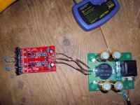
The drop over the current setting resistors R1, R7 is also a bit different. Maybe they can be adjusted to make the output voltage similar,
Today I removed the heatsink... not a big deal after all 🙂
But now I found that hesener did change radically the negative shunt .... I did not know that and my attempt to get the correct voltages might have been very wrong.
Must speak with him to understand the mods.
Yes, I must confess that I did use your boards to test various mods to get rid of those oscillations in the current source. Finally I could not remove them completely, but the new version (r2) does not have that problem at all.
For fear of making you laugh, if you want you can send that board back to me and I will take a look and fix it (in fact, send both so I can compare....)
The joys of being a beta builder - Ricardo you are experiencing them in full beauty ;-)
Done all the PCB modifications for R2 as suggested by all the beta builders, and with a little bit more processing the group buy should start soon now ;-)
I know from at least one happy beta builder that the sound of his R2's is very nice and still improving a little bit, so its definitely a winner! Comparing the BOM cost (probably around 100 euro) to the quality I think it is hard to beat.....
I know from at least one happy beta builder that the sound of his R2's is very nice and still improving a little bit, so its definitely a winner! Comparing the BOM cost (probably around 100 euro) to the quality I think it is hard to beat.....
Yes, the sound from the R2 is amasing. I would be hard pressed to build a better stage.
There is of cause the option to use extremely expensive parts like Vishey bulk foils and Black gates plus aged silver wire. The Preregulator can also being blown up to any size.
It´s time to buy a better turntable, arm and cartridge boys. That can be VERY expensive.
There is of cause the option to use extremely expensive parts like Vishey bulk foils and Black gates plus aged silver wire. The Preregulator can also being blown up to any size.
It´s time to buy a better turntable, arm and cartridge boys. That can be VERY expensive.
Also older high output MCs from Audio Technica. Andre`, our russian friend had one in his Frickelfest system last year. That really rocked the place in a heavy modified Lenco L75.
He found it in the waiste, after 20 years of sitting there. There are a lot of great cartridges from the 70th. Sony, Dynavector, Denon etc. That was the golden age.
He found it in the waiste, after 20 years of sitting there. There are a lot of great cartridges from the 70th. Sony, Dynavector, Denon etc. That was the golden age.
I remember that Thelen in Wuppertal had a huge box with used cartriges he collected over the years. Visit him and look if you find something for free.
I am catching up with this amazing thread!
I think this is one of the best si far!
Reading the various version...
I was very intrigued by the starless balanced topology (balance in/ balance out).
I was wondering why it was never further developed.
If it was could anybody please link me to the final schematic? Or otherwise I would me more than happy to interact and help prototyping making measurements and pcb!
That seems to be such a neat schematic..
Stefano, i have seen that you send me a PM. My box is full but that will be solved soon.
I was working with Sampler on a balanced in - balanced out.
We gave it the name "Masterpiece". There is a schematic somewhere, i have to find it.
The plan is to finish the Paradise R2.
When the beta phase is over and enough work satisfactory we can reconsider the Masterpiece. That is then the final design i would like to finish.
You can search of cause the schematic we already have and we can work together parallel to the Paradise if you want to contribute. My time is limited though for consulting on that at the moment.