LED's do the LED's it's x'mas (even though it may not be the cheapest) Maybe 2 green and 2 red one's (again it's x'mas)
Cool. I like leds and this way we avoid zener noise in the opamp psu but I would avoid blue ones.
I experimented a lot with leds on series regs and the lower noise ones are yellow / orange. mine have 1.9Vdrop at 20mA so I will use four for each rail.
I experimented a lot with leds on series regs and the lower noise ones are yellow / orange. mine have 1.9Vdrop at 20mA so I will use four for each rail.
Last edited:
you bet.....
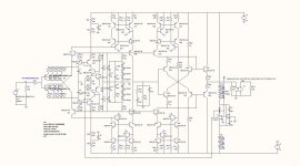
here are the schematics of the preamp and regulators, please take a look if everything is correctly captured. I will start floorplanning with these versions now. I believe the consensus was that the transformer, rectifier and bulk caps are supposed to be in an external enclosure, correct?
enjoy.....
Attachments
you bet.....
here are the schematics of the preamp and regulators, please take a look if everything is correctly captured. I will start floorplanning with these versions now. I believe the consensus was that the transformer, rectifier and bulk caps are supposed to be in an external enclosure, correct?
enjoy.....
In the power supply
R105/205 originaly 500 Ohm kan be 470 Ohm
R106/206 should be 2K or 2K5 trimmers to adjust the output voltage
Otherwise it seems o.k.
Regards,
Frans.
you bet.....
here are the schematics of the preamp and regulators, please take a look if everything is correctly captured. I will start floorplanning with these versions now. I believe the consensus was that the transformer, rectifier and bulk caps are supposed to be in an external enclosure, correct?
enjoy.....
Also change the BC550/560 to BC327/337, that is more in line with preamp. Just for fun 🙂
Last edited:
On first sight the schematics look right.
I will print them out and look more careful later.
Please make space for 4 Leds in series before the servo, just in case somebody is not comfortable with the blue Leds. For some servo ICs we have to drop to plus-minus 15V.
For example the AD825 can stand only plus-minus 15V. Some say it has magical properties as a servo because it has an open loop bandwidth of 10kHz. With 12nV/qHz it is a bit noisy though but that does not play a big role here.
transistors changed to BC327/337, resistors to 470, two trimmers with 2k/10turns, LEDs added
at this point it looks like the 100x160mm PCB might be a little too small.... we'll see....
at this point it looks like the 100x160mm PCB might be a little too small.... we'll see....
Last edited: