Joachim,
A nice servo trick is to connect both the sense and force connections of the servo to the same point, the output. It's like the servo nulls it's own input and there is no impact on the rest of the circuit.
I've used it a few times and even if it looks funny it works great!
I'll put a small diagram together for later.
Edit: attached
jan
Joachim,
I looked again at the circuit I and think I made a mistake. I thought the output was a current output but it is a source follower. That means that my clever 😱 servo will not work at that point. It needs a high impedance point. It would work on the input to your RIAA network (R17 in the circuit I saw).
jan didden
Thanks Jan. Sure, you are right. I will try it out. I already tried my version and the time constant influences the RIAA. That can be corrected by changing the values in the RIAA. I will try if your version has the same effect.
Thanks.
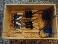
Here is the "Problem Child". It is basically an MPP Summer 2011 2 Stage with two Salas regulators with yet another output buffer. Curiously it worked with only one regulator. With two it gets hot and the sound is sharp. See my humble effort to damp with series resistors.
Here is the "Problem Child". It is basically an MPP Summer 2011 2 Stage with two Salas regulators with yet another output buffer. Curiously it worked with only one regulator. With two it gets hot and the sound is sharp. See my humble effort to damp with series resistors.
Attachments
Thanks.
Here is the "Problem Child". It is basically an MPP Summer 2011 2 Stage with two Salas regulators with yet another output buffer. Curiously it worked with only one regulator. With two it gets hot and the sound is sharp. See my humble effort to damp with series resistors.
That one is special V1 for DCB1, has 100uF lytic cap as output termination. Has plenty of phase margin, and uses its output cap's ESR as damping. If the rails at the load side have small fast caps across to grounds shorting the outputs ESR, series inductors, reactive whatever, margin could have been eaten out, maybe one could just take it, but two could have formed some damping impedance drop path beyond their phase margin handling. Hot and sharp is tell tale oscillating. Try higher ESR output caps on the PSU boards, see what can be adding complexity on the load's rails, have nothing in series on the rails. What can be common and suspect between channels on the rails? Keep the scope on the rails looking for a flat line when AC coupled scope input is selected while trying. This one you got its very seldom it oscillates, had been used widely by people with very diverse circuits, surely you will find a way to apply it better even in an odd situation I trust. One working solo properly already is a good sign.
Thanks.
Here is the "Problem Child". It is basically an MPP Summer 2011 2 Stage with two Salas regulators with yet another output buffer. Curiously it worked with only one regulator. With two it gets hot and the sound is sharp. See my humble effort to damp with series resistors.
Crazy mousebox, can't believe its "sharpness" ...
I see one blue mouse 😉
Hi Joachim,
I think I see a blue and a black mouse, IMO they are the culprit !
Please be gentle and kind to them. I love animals 😉
Tjuus,
Audiofanatic 🙂
Thanks.
Here is the "Problem Child". It is basically an MPP Summer 2011 2 Stage with two Salas regulators with yet another output buffer. Curiously it worked with only one regulator. With two it gets hot and the sound is sharp. See my humble effort to damp with series resistors.
Hi Joachim,
I think I see a blue and a black mouse, IMO they are the culprit !
Please be gentle and kind to them. I love animals 😉
Tjuus,
Audiofanatic 🙂
They are the transformers sans the 230V cables. Yes, this stage is suffering from some juice.
A bit late, may still be of interest
Takman Resistor Audio Patent
Doesn't mention endcap/lead material
Stax Audio Resistor took a very different tack
Rgds
James
Takman Resistor Audio Patent
A resistor 1 is used in high-fidelity amplifiers for audio equipment. The resistor 1 includes a cylindrical resistor body 2, a tubular sheath 3 into which the resistor body 2 is coaxially inserted, and a conductive film portion 31a formed on the inside surface 3a of the sheath 3. The conductive film portion 31a faces to a resistance film 22 covering the surface of the resistor body 2 with an annular space 6. An insulating slit 32 is formed at a central point along the resistor axis 1a, separating the conductive film 31 into left and right parts that are electrically isolated from each other. The sheath covering the resistor body 2 prevents distortion of signals in the resistance film 22 caused by extraneous electrostatic induction charges.
Doesn't mention endcap/lead material
Stax Audio Resistor took a very different tack
Rgds
James
The TAKMAN RTM are capless MELF resistors....But what kind of contacting they have made I am not sure about, as the PDF datasheet does not tell in english...and I cant interpret the Japanese...(could Google translate it, but info is in a graphics file so not translatable)
http://www.takman-e.co.jp/pdf/rtm.pdf
http://www.takman-e.co.jp/pdf/rtm.pdf
info in graphics file
The middle parts reads 'metal', the first and last parts in traditional Japanese are not clear enough to make out.
I'am sure its not iron or steel based...more like nickle copper or tin..that can be plated on the ends for form a solder-able contact layer.
not sure about the nickle sound-vise. as the tests i have done with my loudspeaker terminals clearly indicate that nickle as a barrier layer under gold is not as good as gold without the nickle...
but surely removing the magnetic eddy-current creating steel-endcap on the MELF will be a good thing...and to my limited knowledge surely better, regardless of the possible nickle use...🙂
Last edited:
watch this.....
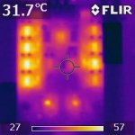
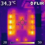
Hi, in the process of building my Hi-Z FPS phonostage, and when doing some initial testing I stumbled across something quite interesting. Attached IR pictures show that the 8x NE5534 have quite different temperatures, ranging from 41C to 57C (!) with no signal.
Datasheet says their idle current is 4...8mA. No oscillations observed (of course I checked). Then I swapped two opamps, and the temperature stayed the same for the same opamp, meaning it has nothing to do with the design or the PCB. (check out the lower righthand corner of the attached pictures where the opamps were swapped, all others stayed where they were)
Now, given that theses guys now operate at vastly different temperatures, may that have an impact on the paralleling, the balance of the circuit, the sonics? Don't know.... Have 30pcs on order and when they are here I will stuff one channel with matched opamps, the other one with unmatched, and do some comparison...
Anybody ever came across that issue? I'm a little puzzled...
Attachments
Interesting! Possibly the varying supply current is the cause; a variation of 1:2 in dissipation must have a temperature effect. Although I wouldn't expect many showing the max of 8mA.
Maybe use different opamps from your stock and see if the variations remain as high.
Edit: The thermal R for a DIP08 is about 60 degrees / W IIRC, so your 16 degr delta temp could be caused by about 0.25W dissipation difference.
Taking a delta supply current of 4mA with +/-15V supplies would give a delta dissipation of about 0.12W so can only explain half of the 16 degrees temp difference. Hmmm.
jan didden
Last edited:
Makes me wonder how images of me Mr Self amp would look like, unfortunately i don't have a Flir yet.
(ah, such a step up from Swarovski military night vision items 20 years ago. Mega Drool => FLIR SYSTEMS, INC. Voyager II Long-Range Thermal Night Vision System at West Marine )
(ah, such a step up from Swarovski military night vision items 20 years ago. Mega Drool => FLIR SYSTEMS, INC. Voyager II Long-Range Thermal Night Vision System at West Marine )
Hesener, i am aware of thermal differences in that design. 57° is a bit extreme of cause.
Our prototype stage had 1 Opamp quite hot. It is easy to simply exchange it. Fortunately the NE5534A is not that expensive. It will be interesting if the thermal differences affect
sound in any way.
Our prototype stage had 1 Opamp quite hot. It is easy to simply exchange it. Fortunately the NE5534A is not that expensive. It will be interesting if the thermal differences affect
sound in any way.