This is a linear amp and works. Did you try to drive a RIAA shaping network from the output ? Here i see only a resistor.
My Plan is to build this module and try different options for the riaa network. I guess the most elegant way would be to make a 'swimming' network, clamped between out1 and out2 ( the values for the resistors half, and for the caps double, but no matching troubles). I need a balanced to SE converter as well and will try a ugs as a 2nd stage with SE output. I will try with buffers as well.
Rüdiger
The RIAA correction will not work when arranged between two high output impedance points,
best,
A.
That is what i think too and the differential has a 3 dB noise disadavntage, Rüder will find a solution, i am sure.
Jam, when you connect for example my RIAA values to your circuit it will see around 100kOhm in the bass. When your output impedance is not high enough you get a loss in bass. It is like a frequency dependent resistive devider. That is the reason i cascoded the mirrors to get a rise in output impedance by x Hfe.
The RIAA correction will not work when arranged between two high output impedance points,
best,
A.
This is true and there are several options to try, including a blowtorch-style input stage. But the cap values would be huge anyway.
This project has to wait until I finished my simple balanced circuit, anyway.
Rüdiger
Joachim,
Doesn't cascoding mirrors lower the available voltage swing? Probably not a problem in this application......
Jam
Doesn't cascoding mirrors lower the available voltage swing? Probably not a problem in this application......
Jam
That was an interesting thread, and my idea was to plan something quite similar as dicussed in this post:
http://www.diyaudio.com/forums/soli...o-preamp-design-philosophy-3.html#post1520535
Charles Hansen, which I admire for his work, seemed to discard common base stages for MC inputs because of potential currents flowing through the coil.
Again i ask, how much current is too much? Anyone?
and here in the very same thread, my other "plan":
http://www.diyaudio.com/forums/soli...o-preamp-design-philosophy-3.html#post1520687
See also Charles Hansens suggestions some posts later.
Both ideas with the EQ between the + and - signal paths.
Of course, the current mirrors need to see a load much lower than their impedance, so their impedance has no (or very little) effect on EQ. I placed the load between the + and - , should work fine.
Matching of + and - components is not necessary (and not possible because there are none to match.... 😀 )
Btw, my first attempt for a common base input and comments from John Curl here:
http://www.diyhifi.org/forums/viewtopic.php?f=11&t=1160&st=0&sk=t&sd=a&hilit=phono
Tino
Ahem, Jam, no, I didn't start with this project.... 😱 I'll let you know...
Last edited:
In the cacodes you loose Ube ( ca. 0.7V ) plus the voltage you drop in the emitter resistors what is not much. You can simply raise PSU voltage if you want the last drop of juice. Zinsula, i answer later, i am too busy at the moment. I am using commen base not any more for new designs although the DC Offset problen can be solved.
Zinsula your BJT design is balanced so you can minimise DC Offset by selecting for Hfe.
In your Fet design you solved the balanced RIAA problem by shunting resistors to ground.
Yes, this should work. The resistors are in series with the RIAA though ( actually resistor value evided by two if they are similiar. That will flatten out the RIAA at some high frequency. That can be solved by an aditional resistor in series and a cap to ground.
Maybe just a cap paralel to the resistors whould work too.
Joachim,
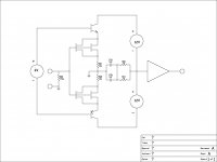
The Spectral seems kinda 'old school' Hitachi topology and is probably noiser due to the differential pair, was gain adjustable for MC use or was there a seperate head amp?
Going back to current mirrors. it might worth investigating the best option......
http://www.odyseus.nildram.co.uk/RFIC_Theory_Files/Current_Mirror.pdf
unfortunately the enhanced Wilson is not analysed.
Last edited:
From Wikipedia -
(Adding a fourth transistor to the Wilson current mirror (as shown in the diagram to the right) improves its linearity at higher current levels. It accomplishes this by equalizing the collector voltages of Q1 and Q2 at 1 Vbe. This leaves the finite beta and voltage differences of each of Q1 and Q2 as the remaining unbalancing influences in the mirror.)
You are correct about the output impedance of a cascoded mirror being higher.
Regards
Jam
PS. All this math is way beyond me....I should have paid more attention in school.😱
Attachments
Last edited:
Thanks for posting the paper about current mirrors. I add the emitter resistors also because the current in the two legs is better balanced when the transistors are not well matched. There is a plethora of other current mirror designs but actually your solution is working well too.
I am not sure what vintage that Spectral circuit is and they may use something more modern today. I asume this is an MM input. The 100 Ohm resistor does the noise no good for low impedance use and the diffential stgae has 6 dB more noise compared to a parallel symmetric circuit with the same amount of input devices.
I am not sure what vintage that Spectral circuit is and they may use something more modern today. I asume this is an MM input. The 100 Ohm resistor does the noise no good for low impedance use and the diffential stgae has 6 dB more noise compared to a parallel symmetric circuit with the same amount of input devices.
I cronological order i then tryed what i can do with feedback and developed a discrete INA. It got the FPS phonostage described in Jan Diddens Linear 0. It has a Transconductance and a Transimpedance input and is fully balanced from input to output including the RIAA. The Transconductance input is DC coupled throughout and the Transconductance input is AC coupled at the input. The Linear Audio 0 volume has a photo of the PCB on the title page. The layout is done by Ward Maas of Pilgham Audio. He will also supply a halve kit that has an external PSU in the form of the Jung-Didden Superregulator. The technical data of that design are state of the art. Configured as a linear amplifier it can be used in low noise intrumentation.
Tonight i mounted my Olympos so over the weekend i will listen with my best cartridge. I am very much looking forward to it.
Today i did not find much time to listen to the Olympos but i listened more to my open loop buffer. I compared it to a short circuit. Yes, i just jumpered it from input to output.
I used my Pioneer universal player as transport and my Hoer-Wege DA converter that already has the excellent LME49600 buffers on board. Diffence was much smaller then using my Pioneer from its analog output so a good buffer helps to drive my 5m cable. With the buffer jumpered the sound was a tiny fraction cleaner and more focussed but i whould not swear on it. The OL buffer on the other side had a more robust sound especially in the bass and the stage was bigger and more spacious at the expense of some focus precission. Musically i liked the buffer slightly more so i think the job is done. Put directly behind the analog output of the Pioneer that difference was more dramatic so this buffer is very good to make a weak output stronger when driving a demanding load. With an already strong signal the buffer does not add much and it does not take away much so i whould say it is 95% transparent. The last bit of performance coud come from other component choices or taking a better PSU then the LC Audio Low Noise Supply that i still use as my benchmark.
I used my Pioneer universal player as transport and my Hoer-Wege DA converter that already has the excellent LME49600 buffers on board. Diffence was much smaller then using my Pioneer from its analog output so a good buffer helps to drive my 5m cable. With the buffer jumpered the sound was a tiny fraction cleaner and more focussed but i whould not swear on it. The OL buffer on the other side had a more robust sound especially in the bass and the stage was bigger and more spacious at the expense of some focus precission. Musically i liked the buffer slightly more so i think the job is done. Put directly behind the analog output of the Pioneer that difference was more dramatic so this buffer is very good to make a weak output stronger when driving a demanding load. With an already strong signal the buffer does not add much and it does not take away much so i whould say it is 95% transparent. The last bit of performance coud come from other component choices or taking a better PSU then the LC Audio Low Noise Supply that i still use as my benchmark.