Because this is not a remote sensed board and is affected a lot on its main target which is extended low Zo. Was made for its partner buffer on board within cm, not intended as general reg, but people wanted to use it as such too after the GB. Did you do that leg change on a positive side's Jfet as in the instructions picture?
I understand.
Should I modify the board and then use a "sense" wire, like in your design at post #1656?
Yes, I did the leg change for the + J-fet.
Wkr
SAm
Should I modify the board and then use a "sense" wire, like in your design at post #1656?
Yes, I did the leg change for the + J-fet.
Wkr
SAm
This is most interesting because i like the Hypo and the LC Audio too. I will try Jan Diddens Jung Reg too.
I understand.
Should I modify the board and then use a "sense" wire, like in your design at post #1656?
Yes, I did the leg change for the + J-fet.
Wkr
SAm
If you can be handy in executing such a modification it will be best for your sonics even against very short 2 wire connection. Its 4 wires after that, or 2 and a sense coax. At least use twisted pairs.
This is most interesting because i like the Hypo and the LC Audio too. I will try Jan Diddens Jung Reg too.
Did you start building your Lab PSU double mono 4 wire adjustable Vout V1?
No, not yet. I am still working a bit on my open loop buffer and had a long and important meeting. At the moment i can not spend much time on DIY but looking into PSUs is on the agenda anyway.
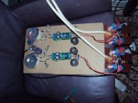
Today was the first time i put the Open Loop Reference Buffer 4 into the system. Until now it existed ony in simulation and on the bench. For safety the class a output stage idles on 15mA and i will try to raise that up to 100mA while listening and measuring. The only time i had listened to various settings of the iddle current in an output stage was when i developped my headphone amp. It sounded better and better, especially in dynamic slamm and in the bass until i hit 75mA and then nothing more exiting happened. But that was with the 60 Ohm load of my AKG701. This time the buffer has to drive a 5m video cable and a 10KOhm pot plus the input of my active woofer so i may come up with another optimum. I also have some issues with the Leds that bias the circuit. Some of them light up bright and some are quit dimm. Maybe i mixed up high efficiency and standart types but instead of finding that out i will build a second set of buffers where i check that right away. What i did the first time too is that i totally seperated the two channels. I have monoblocks and only at the input of my woofer crossover is a common ground. Normally, even when i do a double mono circuits i do a common ground somewhere on the PCB. This time i am able to experiment with a jumper. I listened only breefly and with low volume because my wife is already sleeping. I could hear no hum or hiss, that i can say but the sonic evaluation has to wait until tomorrow. I will also listen against a staight wire bypass. The buffer is then at a slight disadvantage because it looses around 0.25dB of gain. When big differences arise i can of cause make the gain similiar with the pot. See a photo of the setup in the next post.
Try out IR LEDS some time. Best in noise. And you will not see which one is dimmer. End of worries.
I need a certain voltage drop and a certain current through the Leds for minimum distortion. I use high pinsh off voltage Fets that have a big difference in bias for the same GM so i am a bit limitted in choices of the Leds but i wanted to try IR anyway.
You mean that you change the current through LEDs bias voltage references for cascode bases etc. by adjusting their current sources, and you measure different THD on the audio output? Or you refer to some audible effect because the LEDs change noise density and spectrum?
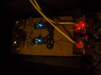
Here is a picture of the buffer, with and without flash. I let it burn until tomorrow and then listen. I have two hours left so i will work on the +-17V Hypo. The picture shows the current state. 200 Ohm test resistors in the minus feed not installed yet. I have to go again through the sugestions.
Attachments
No, i use some of the Leds in the signal chain for current feedback and low impedance steering. Sorry that i can not tell more. One of my friends said : 99% for me (DIY) and 1% for god.
That's another use then. But if the LEDS are from same intensity batch and Vf matched, then it must be different currents. One or another. You got to be sure by installing new LEDS from sure batch first. But I have also seen a 1.75Vf LED surely dimmer than a 1.82Vf LED from same bag for 5mA for instance.
Good sugestion, i will measure the batch before i install. Anyway, the buffer is working and the Leds that do the dirty job are similiar if not ideal still. Idealy i whould need a Led
( or a string of two ) that drops 3.2V at 3.5mA so you see my dilemma. A blue one ? A mini string of IR ? Who knows.
( or a string of two ) that drops 3.2V at 3.5mA so you see my dilemma. A blue one ? A mini string of IR ? Who knows.
I tryed two red ones in series that should give 3.6V and that is close enough but they where starving in the circuit and gave only 1.8V in total. I ordered a batch of red and green in high efficieny and normal. Not a big issue, i have time for this experiment and will find a solution as usual.
setting the Hypo to +-17V without load was not a big deal. I got 17,3 and 17,4 volt fast and easy. Connecting the ULN phonostage the voltage dropped to 9.7V positive and 15,5V negative so it draws more current from the positive side. Offset management was still not upset and i measured the same values as before. That is a good experience because that offset had caused me lots of trouble in the beginning. I will make the rest of the adjustments next day. By the way one shunt mosfet gets now warmer then the other but that is logical. Slowly i get into it. It´s fun by the way.
Give it a good margin of CCS:Load. 2:1 if it can take the heat I would recommend. Measure load current with 317/337 handy PSU in each circuit before you set Hypno's CCS for different CCTs. It will save time in resetting.
*Blue LEDS are noisy compared to Red etc. Best for noise are IR. Given that you got good makes and batches for best noise from each color.
*Blue LEDS are noisy compared to Red etc. Best for noise are IR. Given that you got good makes and batches for best noise from each color.
I found an Osram SFH409 that drops slightly over 1V at 3.5mA, so a string of 3 could work. I found another IR Led that only needs 0.4 mW/sr @ 1.2V.
I have now made more listening tests with the OL buffer 4 prototype and now i understand what PMA is saying. As long as you have not heard something better the OPA134-BUF634 is just fine. Switching to buffer 4 reveils a much bigger and more populated stage. Dynamic slamm is much enhanced and the Opamp buffer sounds clean but also lifeless and sterile in comparison. The question that now arises is if that is a function of using heavy voltage feedback or rather not as Allen Wright is fiersly advocating. I have just drawn a schematic that combines an Opamp with buffer 4 to make it a high feedback voltage follower and then i will do the listening all over again.