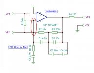
This is the circuit i am working on. First i will build it with integrated Opamps and later i will use the Josi that is made of discrete components. Circuit values of the RIAA are not shown yet because i first will build and measure it. The output can be a transformer, a differential stage or passive. Coupling from input stage to RIAA could be made DC coupled but i decided on the most simple solution.
Attachments
Hi Joachim -
what is your experience with signal transformers, have not you find any sound degradation. Thanks.
Best regards,
what is your experience with signal transformers, have not you find any sound degradation. Thanks.
Best regards,
I use a transformer with only 6dB gain. Used that way it is very extended in the treble. In the bass you nead high inductance and for low noise you nead low impedance so you can imagine that i use a big core. What you may like to know is how high the didtortion is. That depends on the core material. A core that delivers high inductance may have problems at low level because of Barkhausen effect so the lower the level goes, the more noise and distortion you get. My goal is to get lower noise then 0.3nV. The transformer we use has 1.8 Ohm DC impedance, so it may be posible. Distortion at high level should be not a problem because an MC cartridge does not deliver high voltage, but at very low level resolution could be finite. Anyway, an active MC input stage with NFB stands under suspision too concerning ultra low level resolution but i should not say that here right in the open because it it hard to prove that with measurements.
I have a long term project to substitute all integrated Opamps in my system for discrete circuits. I am perfectly happy with the performance but a discrete circuit is more fun and a bigger challenge. One project is the JOSI Opamp but it is made with a lot of expensive
and partly obsolete parts. I was able to buy them NOS but sometimes i may need something more afordable and simple. Of all the circuits i have seen lately i like PMAs Fet Dispre very much. It uses a diamond buffer and i have alaborated on that circuit in my headphone amp. It works very well but is not really simple any more. I had made good experiences with my modified JLH buffer that is much simpler and performs very well. I hear it each day in my default JGSelf preamp. I had made a version in the meantime with medium power Video transistors that can stand up to 70mA of idle curent with +-24V supply so i thought this could be a candidate for the Fet Dispre. The circuit i show here has no values and i omitted all compensation, filters, servos etc. just to show the basic topology. You have to scroll to the second page to see it.
and partly obsolete parts. I was able to buy them NOS but sometimes i may need something more afordable and simple. Of all the circuits i have seen lately i like PMAs Fet Dispre very much. It uses a diamond buffer and i have alaborated on that circuit in my headphone amp. It works very well but is not really simple any more. I had made good experiences with my modified JLH buffer that is much simpler and performs very well. I hear it each day in my default JGSelf preamp. I had made a version in the meantime with medium power Video transistors that can stand up to 70mA of idle curent with +-24V supply so i thought this could be a candidate for the Fet Dispre. The circuit i show here has no values and i omitted all compensation, filters, servos etc. just to show the basic topology. You have to scroll to the second page to see it.
Attachments
Hi Joachim -
the buffer looks good. You made some changes in the VAS - are you sure they are right.
Best regards,
the buffer looks good. You made some changes in the VAS - are you sure they are right.
Best regards,
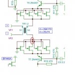
I do not exactly know what you mean. Maybe a resistor to ground is missing on the input of the buffer. Here i post again one of the linestages i am using. Here i use darlingtons at the output. - 3dB is at 16MHZ and distortion is low. For higher current i use the 2SA1407 and 2SC3601 video transistors.
Attachments
1) If the buffer has +1 gain (or any positive gain), then the feedback in your circuit is positive.
2) what is the reason of resistors in emitters of VAS transistors.
2) what is the reason of resistors in emitters of VAS transistors.
Sorry Pavel, i have drawn the circuit wrong. Here comes the correct version. In my buffer the resistor from base to emitter sets the idle current in the Fet. ca 300 Ohm is ok.
The resistors from source to output set the idle current in the bipolars. Depending on transistor they can be as low as 10 Ohm. The bipolar does a DC bootstrap on the Fet and provides 100% local feedback so linearity of this simple circuit is very good.
The resistors from source to output set the idle current in the bipolars. Depending on transistor they can be as low as 10 Ohm. The bipolar does a DC bootstrap on the Fet and provides 100% local feedback so linearity of this simple circuit is very good.
Attachments
I am preparing for the Frickelfest. I will bring my MPL light with X-Dipole woofer and will use my LA Audio Monoblocks plus the JGSelf that is now working in a nice cabinet. I have now an active double mono PSU and that sounds better then the two lead acid batteries i was using. Maybe it is because the double mono use. I will also bring the cheap musicians phono and the MPP Nova. I also have a little Tripath amp to compare it to the tubes. Testing the MPP Nova with the linestage of the JGSelf i was not totally happy with the hum performance. I solved that issue with rearanging the elcaps that filter the Leds of the input cascode. I connected them now to ground instead of the PSU and the Humm disappeared. Bias after trimming ( ideally with the cartridge connected because that has a small impact ) i can now DC couple. I had to raise the servo authority somewhat, i am using now 2kOhm at the output of the servo. I finetuned the RIAA with aditional 10nF caps. Over 200Hz accuracy is better then +-0.1dB now, my measurement limit. There is a tiny hump ( +0.3dB ) at 100Hz but i left that in.
Attachments
I prefer balanced. Especially the INA type. It has 3dB more noise then an unbalanced stage with the same amout of active input devices but somehow has better low level resolution and more raw dynamics.
I am preparing for the Frickelfest.
Hi Joachim,
could you elaborate a bit. Where is it and when.
Thanks,
I prefer balanced. Especially the INA type. It has 3dB more noise then an unbalanced stage with the same amout of active input devices but somehow has better low level resolution and more raw dynamics.
It's exactly the same difference that I feel when use mine system all balanced playing digital records or streaming from Vaio laptop, I doubted if will be the same in analog domain that's the reason I asked you, the answer possibly be that balanced adds 6dBs more of gain (more dinamics like your & mine subjective opinion) & avoid all ground loops problems (better low level resolution...also mine subjective opinion)
Pavel, the Frickelfest has a webpage, simply google Frickelfest. It is in the north east of Germany at the Elbe.
I think the advantage of the INA is common mode supression and it can swing 6dB more voltage without overload but that is only theory. I think it also has the advantage that the gain resistors are not connected to gound. At such low levels as -146dB/V ground polution is absolutely to be avoided.
I think the advantage of the INA is common mode supression and it can swing 6dB more voltage without overload but that is only theory. I think it also has the advantage that the gain resistors are not connected to gound. At such low levels as -146dB/V ground polution is absolutely to be avoided.
I am working still on the Balanced INA Inductive but the "triple INA" i designed seems to have more problems then it solves. DC conditions are hard to handle, so is stabilty. I redesigned and simplified the circuit. After the 50Hz pole of the inductor i do the shelf passive now. The output stage also does the Balanced to Unbalanced conversion now.
That way i safe 2 Opamps or one Opamp and one Transformer.
I also redesigned my Ultra Simple Phonostage. I am trying a floating input that has the advantage of zerro common mode distortion. I have seen such a circuit first in a Phonostage that Dimitri did in the 90th.
That way i safe 2 Opamps or one Opamp and one Transformer.
I also redesigned my Ultra Simple Phonostage. I am trying a floating input that has the advantage of zerro common mode distortion. I have seen such a circuit first in a Phonostage that Dimitri did in the 90th.
Attachments
I am working still on the Balanced INA Inductive but the "triple INA" i designed seems to have more problems then it solves. DC conditions are hard to handle, so is stabilty. I redesigned and simplified the circuit. After the 50Hz pole of the inductor i do the shelf passive now. The output stage also does the Balanced to Unbalanced conversion now.
That way i safe 2 Opamps or one Opamp and one Transformer.
I also redesigned my Ultra Simple Phonostage. I am trying a floating input that has the advantage of zerro common mode distortion. I have seen such a circuit first in a Phonostage that Dimitri did in the 90th.
Joachim,
You've done a lot of work here, I just caught up with this thread and am
amazed how much you get through.
WRT the transformer IP version, a few comments:
- With the transformer connected as such between jfet sources, in common
gate config there will be significant DC current running through transformer
secondary. This will cause added LF distortion, especially with a high nickel
core as it saturates easily. Not a good idea IMO.
- The reflected impedance to the transformer primary, even with a low
ratio (1:2) will be very low, is this your intention? Prim Z = whatever Z
the secondary sees / turns ratio squared. Obviously DC winding resistances
have to be factored in aswell.
- The schematic capture program appears to be making connection errors.
Ref below.
For the transformer version, why not take advantage of the free gain the
transformer provides and simplify the whole CCT. You should be able to
basically scrap the whole discrete front end and just run a 3 low noise
opamp INA straight after transformer. Also since the secondary has low DC
resistance, you should be able to get by without any coupling caps or
servos, possibly just an offset trim. Do the RIAA eq around/before 3rd 'summing' amp.
cheers
Terry
Attachments
Thanks for finding out the connection errors. Yes, very good idea to get rid of the input stage. Maybe then i use a transformer with x 5 or x 8. For the INA OPs i am planning to use my JOSI discrete Opamp.
New Circuit Ideas
I am just comming back from the Frickelfest with new ideas. I was sitting for hours with two very talented circuit designers and got some nice input. Today i present a new version of the MPP with more gain because the collector resistors are substituted with constant current sources. An All In One Go Transimpedance RIAA is now posible. Also see the latest version of my improved JLH buffer.
I have also posted a new version of my Transformer Balanced Discrete INA on the Blowtorch thread.
Attachments
I am just comming back from the Frickelfest ....
Joachim,
Did you take your speakers to the Frickelfest?
How was the reaction from the listeners?
Regards, Allen