I used my lab supply so there was no input cap unless the lab supply has one inside.
I used a 10uF-50V Panasonic FM at the output plus a 220 Ohm loading resistor.
When you ask my goal :
I am happy how your original circuit performs in the headphone amp i build.
I am interested though how the output spectrum looks ( can it be improved ? ) and if we can avoid rather big electrolitics. There are now big values of film caps coming on the market that are rather small, for example from Wima.
This ones go to 6.8uF in SMD :http://www.wima.de/DE/WIMA_SMD_PET.pdf
They are a bit wider and deeper but not as high.
They are a bit wider and deeper but not as high.
Mouser has the 4.7u/50VDC in stock. I bought a bag of the 10u/16V from TTI and they're almost all gone -- with lm4780 amplifier kits.
Now it gets expensive :
https://www.distrelec.de/folienkond...0-vac/evox-rifa/smc16-5-335j50c31-tr24/828208
A 3.3uF PPS SMD. PPS is lower distortion then Polyester and has a very stable temperature coefficient, a Polycarbonate substitute.
https://www.distrelec.de/folienkond...0-vac/evox-rifa/smc16-5-335j50c31-tr24/828208
A 3.3uF PPS SMD. PPS is lower distortion then Polyester and has a very stable temperature coefficient, a Polycarbonate substitute.
K-Multiplier link
The file servers have been working fine, this whole time; but, between you and ostripper, the smaller scale DNS servers that run fidelityforce.com tend to throw the towel when college classes started referencing your works. The outage lasted 6 hours before the backup caught it and it came back online. Your signature link is back up and running at this time. In August, it will be possible to re-register fidelityforce.com and add Anycast DNS for more durability. Meanwhile, I suggest using this link, which is very durable.
Anyway, your next article that I'd like to see is Kosine compensation, and some high/low examples for both current and pitch so that people like me, who can't calculate as an engineer, might could still manage to use the information. Um. Pretty please? If you want to monetize the content, in some way, that's fine too, because your compensation circuits are quite valuable to improve imaging without adding any caveat. In that, I believe it is unique.
The K-multiplier has blocked noise and by using it, you have also blocked the "baby out with the bathwater" caveat of over-reliance on amplifier power noise rejection features. Does that match with your theory?
Blocking both noise And caveat is awesome!
And, it gives me a question:
So far, so good for V+ and V-; however, they are a quarter of the signal apiece. The other half of the signal is the 0v. That was approximate, but the question is, can we stabilize the 0v too? When I look at it, the 0v line connects from the music source device and then right into the amplifier power supply, which appears to be something that should not be done that way. What alternatives do we have? Some form of stabilizing rail splitter approach? Multiple rail splitters? I don't know.
Not so much: Keantoken home page the mirror at Startfetch.com, which is running on the AnyCast network distributed DNS, plus GoDaddy distributed servers, for nonstop worldwide coverage.keantoken said:Unfortunately the link in my signature is down.
The file servers have been working fine, this whole time; but, between you and ostripper, the smaller scale DNS servers that run fidelityforce.com tend to throw the towel when college classes started referencing your works. The outage lasted 6 hours before the backup caught it and it came back online. Your signature link is back up and running at this time. In August, it will be possible to re-register fidelityforce.com and add Anycast DNS for more durability. Meanwhile, I suggest using this link, which is very durable.
Anyway, your next article that I'd like to see is Kosine compensation, and some high/low examples for both current and pitch so that people like me, who can't calculate as an engineer, might could still manage to use the information. Um. Pretty please? If you want to monetize the content, in some way, that's fine too, because your compensation circuits are quite valuable to improve imaging without adding any caveat. In that, I believe it is unique.
In regards to the headphone amp. Kudos!Joachim Gerhard said:. . . Andrejs design showed that the very good PSU rejection of the Paradise still allows the quality of the PSU to come through in the listening test. Why that happens is an Enigma to me although i have a theory.
The K-multiplier has blocked noise and by using it, you have also blocked the "baby out with the bathwater" caveat of over-reliance on amplifier power noise rejection features. Does that match with your theory?
Blocking both noise And caveat is awesome!
And, it gives me a question:
So far, so good for V+ and V-; however, they are a quarter of the signal apiece. The other half of the signal is the 0v. That was approximate, but the question is, can we stabilize the 0v too? When I look at it, the 0v line connects from the music source device and then right into the amplifier power supply, which appears to be something that should not be done that way. What alternatives do we have? Some form of stabilizing rail splitter approach? Multiple rail splitters? I don't know.
Oh, I definitely have one of those.Joachim Gerhard said:. . . my focus zoo. . .
Last edited:
And, it gives me a question:
So far, so good for V+ and V-; however, they are a quarter of the signal apiece. The other half of the signal is the 0v. That was approximate, but the question is, can we stabilize the 0v too? When I look at it, the 0v line connects from the music source device and then right into the amplifier power supply, which appears to be something that should not be done that way. What alternatives do we have? Some form of stabilizing rail splitter approach? Multiple rail splitters? I don't know.
Oh, I definitely have one of those.
Thanks for the work on the site Dan.
Ground isolation is a job best handled by the amp, not the power supply. A balanced input amp would not need input ground connected to signal ground, aside from some protection diodes. It is possible to make an active virtual ground referenced to input ground, but this ground will have to absorb the entire load current so you are building another amp to ground your amp with. You might as well just do a bridged balanced input amp. That said, it might be practical for something like a headphone amp, but better than other approaches? I don't think so.
An SMPS (switchmode).
Well, they do look convenient, but it might not be convenient.
There's two new additional problems added by using an SMPS.
It will run your signal reference through a common mode choke, which can add a tone control sounding effect.
The signal output of the smps although tiny, is far higher pitched than the effective capacity of the regulator.
I do not know if this will help:
Choke, 0v distortion: Possibly, if the SMPS voltage is significantly Much higher than the linear regulator, the sound of that common mode choke may be removed; however, I do not know and you may need additional circuitry to remove distortion at the 0v. Perhaps that rail splitter may simply divorce that choke problem by removing the direct connection to it, but I don't know.
High pitched distortion: Within the LM338 datasheet is "Tracking Pre-Regulator" schematic which will work with the LM317's even better. This can probably expand the capacity of the LM317 to stop the high pitched signal that may have otherwise made the regulator ineffective.
Although the SMPS is theoretically more efficient, it may be more convenient to check out the linear power supply (with snubbed transformer secondaries) much lower pitched output and much lower inductance. I don't know what else to say about that, except that it might be good to do a comparison to solve that question practically.
I will of cause measure the SMPS. The Tracos have a good reputation and i have seen them in very expensive equipment. Anyway, when it does not perform to my standards i skip it.
This is another option :
http://www.ti.com/lit/ds/symlink/tps7a4700.pdf
They also have negative ones.
http://www.ti.com/lit/ds/symlink/tps7a4700.pdf
They also have negative ones.
Hi,
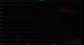
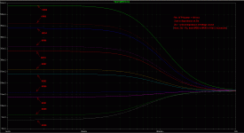
simmed extensively with different schematics and it seems that Kean´s speed-Up Diode is the best compromise on performance vers. parts number count. So I did sims for symmetrical supplies.
So far, we could see a rise in Zout below a very low Frequency towards DC.
I noticed a behaviour regarding DC- and VLF- output impedance which I haven´t understood yet.
Basically the output impedance of the Gyrator depends also on the Rser {Z(output)} of the supplying voltage source, with rising Zout for rising Rser > 1R.
But varying Rser from 0R to any positive value, the minimum Zout of the Gyrator will not be not be lowest at Rser=0Ohms (which is the default in the sims), but at a resistance of about 0R89-0R90Ohms. Here the Zout actually drops below the mean value of Zout in a middle frequency range.
See attached files.
The most linear Zout results between 0R92 and 0R93Ohm.
Kean already mentioned the 1R impedance in an earlier post.
Was this value found by lucky accident, or is there an Theory backing up?
jauu
Calvin
@daniel
The HF-noise may indedd give probs for integrated regs like LM317 et al. They´re simply too slow. But this is where a Gyrator excels.
Imho, the choice for an SMPS makes the useage of an gyrator mandatory.
But then I see no issue -and had none in praxis so far- using SMPSs.
Attachments

you are right, its no longer a cap multiplier but a hybrid. referencing R8 to the output would reverse that, so the circuit could be developed into a cap multiplier with high voltage drop but good noise isolation. in fact, i just played around with the circuit, no real specification in mind...
personally i have nothing against a little regulation, but that depends entirly on the application 😀
I would say, not a capacitor multiplier and not a hybrid, just a regulator. The ground reference is the big difference. This circuit also no longer matches the original question. When you start using a ground reference then you be better of building a simple 'conventional' regulator.
Hi,
simmed extensively with different schematics and it seems that Kean´s speed-Up Diode is the best compromise on performance vers. parts number count. So I did sims for symmetrical supplies.
So far, we could see a rise in Zout below a very low Frequency towards DC.
I noticed a behaviour regarding DC- and VLF- output impedance which I haven´t understood yet.
Basically the output impedance of the Gyrator depends also on the Rser {Z(output)} of the supplying voltage source, with rising Zout for rising Rser > 1R.
But varying Rser from 0R to any positive value, the minimum Zout of the Gyrator will not be not be lowest at Rser=0Ohms (which is the default in the sims), but at a resistance of about 0R89-0R90Ohms. Here the Zout actually drops below the mean value of Zout in a middle frequency range.
See attached files.
The most linear Zout results between 0R92 and 0R93Ohm.
Kean already mentioned the 1R impedance in an earlier post.
Was this value found by lucky accident, or is there an Theory backing up?
jauu
Calvin
@daniel
The HF-noise may indedd give probs for integrated regs like LM317 et al. They´re simply too slow. But this is where a Gyrator excels.
Imho, the choice for an SMPS makes the useage of an gyrator mandatory.
But then I see no issue -and had none in praxis so far- using SMPSs.
This is all true, but now we are back at very low voltage drop (Joachim was allowing larger voltage drops) and high (relatively) value capacitors (Joachim asked specifically for low values).
I would be most scared of this 'Leckstrom 0.3 mA eff. typ. / 230 VAC / 50 Hz' it (most probably) is a capacitor from the internal high voltage supply to output ground. In most CE devices there will be two of these capacitors, one from internal HV-supply and one from the internal HV-supply-ground. But there are more 🙂 possibilities.
Calvin, i am a bit confused but maybe it is only a typo.
So you say that before the K-Multiplier should be a ca. 1 Ohm series resistor.
You specify this resistor with 1uF !
Frans, i know, switch mode supplies are not very popular but i am really fed up to build conventional supplies for my many prototypes. the other solution is batteries but what do you do when you compare 10 different circuits as i sometimes do ?
On the other hand High End manufactures go there and with good results.
I can post some measurements on PSU noise from the new Jeff Rowland equipment that had zero harmonics in the spectrum. That is hard to do with a linear supply.
The measurements i got from Wilfried Kress go only to 1kHz though.
Maybe we get in trouble at RF, who knows.
Calvin, i am a bit confused but maybe it is only a typo.
So you say that before the K-Multiplier should be a ca. 1 Ohm series resistor.
You specify this resistor with 1uF !
Frans, i know, switch mode supplies are not very popular but i am really fed up to build conventional supplies for my many prototypes. the other solution is batteries but what do you do when you compare 10 different circuits as i sometimes do ?
On the other hand High End manufactures go there and with good results.
I can post some measurements on PSU noise from the new Jeff Rowland equipment that had zero harmonics in the spectrum. That is hard to do with a linear supply.
The measurements i got from Wilfried Kress go only to 1kHz though.
Maybe we get in trouble at RF, who knows.
Calvin has defined a '1uOhm' resistor before and after for measurement purposes, it is not an implementation part.
The ground reference is the big difference.
Should read 'The DC ground reference' 😱