do you believe this could be used as a subwoofer driver ?
That looks rather cool.
Motor driven drivers can theoretical go to Zero Hz.
They do not give any frequency response curves so I do not know the benefits really.
There is no hint of distortion profile at any level and frequency so I am confused even more.
Motor driven drivers can theoretical go to Zero Hz.
They do not give any frequency response curves so I do not know the benefits really.
There is no hint of distortion profile at any level and frequency so I am confused even more.
It is an amazing rig anyway......
Now I have a real question for you...
I am modifying a big speaker that uses four big woofers each 4ohm nominal impedance.
I need resulting impedance to be 4ohm..... what would be the best wiring:
Block A (Two in series to get 8ohm)
Block B (Two in parallel to get 2ohm)
1st option:
Block A in parallel with Block A to get 4ohm
2nd option:
Block B in series with Block B to get 4 ohm.
Hope you do not mind to share your knowledge regarding these secrets 🙂
Best
Ricardo
2 in parallel for 2 Ohm each group of two. Then each group in series for 4 Ohm.
2 Ohm plus 2 Ohm = 4 Ohm
2 Ohm plus 2 Ohm = 4 Ohm
I decided to publish another speaker for DIY. I can not imagine that this one will have any commercial success but the idea is too intriguing to be wasted. Watch this space.
I am modifying a big speaker that uses four big woofers each 4ohm nominal impedance. I need resulting impedance to be 4ohm..... what would be the best wiring
Attachments
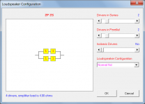
Just to clarify, there is actually no difference electrically between your two options - you could use either one, and obtain the same results, assuming the four drivers are identical. The second option is in effect just the first option, but with the mid points of each A block connected together. Because the system is balanced the voltages at the mid points of each A block are the same, and no current would flow from one block to the other anyway. I prefer the configuration I posted simply because it has the most straight-forward wiring.
I have been working as a professional loudspeaker designer and am proud of my work.
This one (AL THREE) is special because I designed the enclosure using Solidworks and became really good at it. Stenheim Alumine Three Loudspeaker - The Absolute Sound
I had to design several waveguides for the tweeter in order to obtain a better alignment and improve dispersion.
I had the help of hornresp for that also.
I did 14 versions of the filter until I got it where I wanted.
Finally decided to use two different woofers in the same bass reflex enclosure to get the bass to be brilliant.
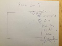
...bass to be brilliant? Sorry, to spoil the party, but it is room modes that fool with even the best laid woofer alignment plans in conventional integrated (sub-)woofer-mid-tweeter systems. Double Bass Arrays, nearfield subwoofer placement or carefully tailored multi subs are the way to go. T.I.N.A.
Maybe I was not very clear.... I needed to increase the upper bass nitidity so:
The Mid driver is a 5 inch device so it can not handle easily very low frequencies and is cut at 300Hz.
At the same time the Bottom Woofer (built with a soft surround) needs to be cut at a relatively low frequency (145Hz) in order to avoid colorations in the low mid region.
To cover the low mid region up to 300Hz, I decided to use a "faster" Top woofer (built with a stiff surround) that complies with the design.
The close technical relationship between the two Bass drivers enables me to use them in the same laminar bass reflex enclosure tuned to 40Hz.
I see what you mean now.
A picture is worth a thousand words.
I have your papers related with speaker placement but did not find anything related to this method.
I will try it asap.
A picture is worth a thousand words.
I have your papers related with speaker placement but did not find anything related to this method.
I will try it asap.
It is a new idea. I am working on an addendum to my setup paper where I also try to cover vertical imaging and Blauert Bands.