They are still recommending it for new designs. This was posted just over a week ago.
http://www.semicon.toshiba.co.jp/solution/audio/poweramp.html
http://www.semicon.toshiba.co.jp/solution/audio/poweramp.html
I wouldn't be surprised if the 2sk389 was in fact alive and kicking. Whatever they tell me here I take it with a grain of salt. The English is not always the best, and rather than embarrassing themselves in attempting to describe a complicated situation they just cut it short and say "discontinued".
FWIW - what other transistors are a close match to the 2sk389? Maybe I can get an equivalent type locally. It's always nicer to play around with stuff that can be replaced easily in case of crash'n'burn 😉
FWIW - what other transistors are a close match to the 2sk389? Maybe I can get an equivalent type locally. It's always nicer to play around with stuff that can be replaced easily in case of crash'n'burn 😉

Looks very nice, would you mind giving us a bit more info about the graph? What were the curve chosen, the Q of the filters, the target frequencies, etc...
Also why is the level at -10? What was the gain configured in the buffers?
Thanks!
Sébastien
Also why is the level at -10? What was the gain configured in the buffers?
Thanks!
Sébastien
Hi,tiroth said:It works.
very nice work.🙂
I won't have the discrete opamps verified until tomorrow as I...mmm...blew up the only one I built so far. [/B]
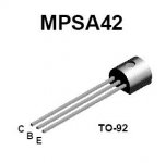
Problem is maybe wrong BJT's orientation if you are using MPSA42 and 92.
Regards
Attachments
Dimensions
The completed dual opamps have a footprint that is just about exactly .930x.930", or about 23.6mm square.
They stand 1.45" (37mm) tall, plus another .1" (2.5mm) if you use the headers I used.
The total height of a MOX board populated with opamps is about 2.25" (57mm), less depending on your use of sockets, etc.
Graph
The graph shows the curves for HP and LP @ 2kHz with Q of 0.5, 0.7, 1.4, 1.7 (on the HP).
Don't pay attention to the absolute gain; I needed enough headroom to show the high Q peaking.
Opamp
Moamps, I have the sinking feeling that you are right. I traced my layout against yours, not thinking that your red traces were problably bottom signal for a single layer board.
Time to fix.
EDIT: The Q values I listed may be wrong. It was rather late last night when I finally got to tracing the curves and I replied from memory. Comprehensive tests are coming tonight.
Hi,tiroth said:.....not thinking that your red traces were problably bottom signal for a single layer board. ...[/B]
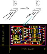
It's my fault too, sorry. OPAMP PCB is designed at the first time for BC550C and BC560C (diferent pinning). MPSA transistors are later placed on board (mirrored), but I didn't made changes on PCB board picture I published in MOX thread.
Regards
tiroth said:EDIT: The Q values I listed may be wrong. It was rather late last night when I finally got to tracing the curves and I replied from memory. Comprehensive tests are coming tonight.
moamps said:
Hi,
It's my fault too, sorry. OPAMP PCB is designed at the first time for BC550C and BC560C (diferent pinning). MPSA transistors are later placed on board (mirrored), but I didn't made changes on PCB board picture I published in MOX thread.
Regards
I hope we can go with the MPSA 42 and 92 since I already have a stock just for this project.MBK said:How about leaving it as is and using BC550/560?
BTW, that was what was shown in Moamp's original schematic.
You could use BC or MPSA parts without modification (you must bend the center lead anyway for the inline package), only the silkscreen is wrong as-is for the MPSA (in proto only). I too have a few hundred MPSA42 and 100 MPSA92 on my desk. 😉
The question is, should the PCB be changed for production?
The question is, should the PCB be changed for production?
roddyama said:I hope we can go with the MPSA 42 and 92 since I already have a stock just for this project.
BTW, that was what was shown in Moamp's original schematic.
Schematic and board, chotto chigaimashita ne? My problem, will address however people see fit.
roddyama said:
I hope we can go with the MPSA 42 and 92 since I already have a stock just for this project.
BTW, that was what was shown in Moamp's original schematic.
Yeah, I already ordered some myself also 🙂
--
Brian
Crossing the leads of 1 or 2 transistors is no big deal. Much like the FET in the A40 boards from Old Colony (back in the day). But to cross them on many pieces is, statistically speaking, asking for trouble.tiroth said:You could use BC or MPSA parts without modification (you must bend the center lead anyway for the inline package), only the silkscreen is wrong as-is for the MPSA (in proto only). I too have a few hundred MPSA42 and 100 MPSA92 on my desk. 😉
The question is, should the PCB be changed for production?
Well, you don't need to cross them, you just flip the whole device around. That is the nice thing about having the base in the center.
I can live with that easily enough.tiroth said:Well, you don't need to cross them, you just flip the whole device around. That is the nice thing about having the base in the center.
BTW, Your doing a great job Tyler, thanks.
tiroth said:You could use BC or MPSA parts without modification (you must bend the center lead anyway for the inline package), only the silkscreen is wrong as-is for the MPSA (in proto only). I too have a few hundred MPSA42 and 100 MPSA92 on my desk. 😉
Hi,
here is MPSA modification example.
Regards
Attachments
I think that crossing the leads might be fine, but if you have a large board order, the extra tooling fee shouldn't be too much extra for getting the layout modified.
--
Brian
--
Brian
You missed it Brian. I was mistaken, the leads do not need to be crossed. It is only that the center base lead is offset toward the flat ("front") of the device instead of the round ("back"). Look closely at Moamps' picture above.BrianGT said:I think that crossing the leads might be fine, but if you have a large board order, the extra tooling fee shouldn't be too much extra for getting the layout modified.
--
Brian
- Status
- Not open for further replies.
- Home
- Group Buys
- MOX-like crossover and discrete opamp group buy