Favoring THAT Corp is not illogical, but don't you mean their THAT1646 or THAT1606 Balanced Line Driver? Why would you use their Balanced Line Receiver for an output application? I'm beginning to see your illogic...For the output my illogical preference is a cross-coupled output using THAT1240.
No I do mean the 1240. I like it because, although a receiver it will drive the sort of line lengths we use and you have one circuit block that will work for SE or balanced input. A bit kooky but I like. The 1646 is also a superb part for a SE input.
My previous statement about the Shure V15V noise is wrong. It would be correct for a Shure V15IV. I forgot Shure greatly reduced the V15 coil resistance from about 1400 Ohms in the older V15s to about 400 ohms in the V15V.
FWIW, the cartridge(s) that I'm designing for are specified with an internal DC resistance of 1000 Ω and 580 mH. They output 8 mV at 1000 Hz, 5 cm/sec.
That sounds very ortofon.
Ray: I have a couple of silly low impedance MMs. One is 30 Ohms DC. I know it's in the realm when vinyl noise is so far above this it's not really worth worry about, but you know how it is 🙂
Ray: I have a couple of silly low impedance MMs. One is 30 Ohms DC. I know it's in the realm when vinyl noise is so far above this it's not really worth worry about, but you know how it is 🙂
Thanks to eBay, I just scored a discontinued Ortofon MC with 3 Ω DC, no inductance listed. It's 0.09 mV at 1000 Hz, 5 cm/sec. I'll be fabricating a PCB for that cartridge using a different schematic.That sounds very ortofon.
Ray: I have a couple of silly low impedance MMs. One is 30 Ohms DC. I know it's in the realm when vinyl noise is so far above this it's not really worth worry about, but you know how it is 🙂
As soon as I started focusing on my MM collection, I'm getting interested in MC. Oh, the dangers of audiophile hobbies and electronics design experience...
Tell me about it. Two years ago I settled on the AT150MLx being my 'high end' MM and an Ortofon S120 for mono duties. I was going to pension off my old MC and run just MM for a few years. Then things started going horribly wrong 🙂. Then I found a nice man in Russia who could fix almost anything and it got worse!
The ortofon MC is likely to be a few uH. Nothing worth worrying about for all but the strangest preamps.
The ortofon MC is likely to be a few uH. Nothing worth worrying about for all but the strangest preamps.
I have not managed to model a MM as any combination of ideal inductors and resistors. The Permalloy material is very frequency sensitive in the audio band. There always seems to be a drop in generator output in the ~5kHz area.
What do you mean by "generator output" above?I have not managed to model a MM as any combination of ideal inductors and resistors. The Permalloy material is very frequency sensitive in the audio band. There always seems to be a drop in generator output in the ~5kHz area.
I am also intrigued. I know that many MM show a dip around that region with a 47k||C load but I don't think its due to frequency selective behaviour.
I am also intrigued. I know that many MM show a dip around that region with a 47k||C load but I don't think its due to frequency selective behaviour.
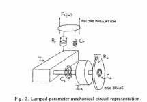
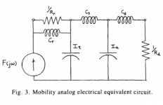
An article in the JAES from 1986 for an MC cartridge, move around the parameters for a MM cartridge:
Attachments
Last edited:
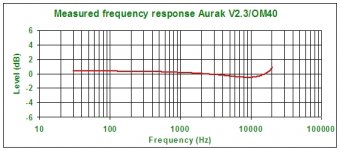
Not sure that helps explain it. The dip is shown on many measurements but not on others (for the same cartridge) but the the only model that matches it is the van Raalte one from linear Audio (image courtesy of LA). But that model fails to explain the attached FR plot done with a transimpedance load on the cartridge which is flat to 100kHz or so. I would like to get to the bottom of it.
Attachments
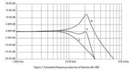
Stanton 681 EEE in a High Fi/Stereo Review by Julian Hirsh, July 1968. I have one of these -- much abused by #1 son who was a DJ -- but it still tracks well. Will pull it off the tone-arm and put it onto the Bode-100 in a few weeks.
http://lcweb2.loc.gov/master/mbrs/recording_preservation/manuals/Stanton (Misc.).pdf
http://lcweb2.loc.gov/master/mbrs/recording_preservation/manuals/Stanton (Misc.).pdf
Attachments

That looks nicely behaved. I note the 500 series shows more of the midrange dip, but still only around 1dB. The rega exact is +/-3dB
I'd forgotten about that. Might be just what we needed on another discussion on this topic Thank you.
I think you would have to look at the exact measurement set-up to decide where the mid-range dip came from. Tone arm resonance? Head shell resonance? Was the response measured using a reference disc? If so, was the EQ ok etc etc.
The HF resonance within reason is easy to understand (cart L, cable C, input amp C if discrete JFET un-cascaded for example. On single ended discrete EQ amps with feedback to the 1st transistor emitter, I would imagine the load moves around a bit as well.) Some of the plots however are pretty horrific - I struggle to see how the measurement could be accurate or well conducted.
🙂
Sorry I missed this thread if only to reiterate that most of the supposed issues with flat recording and software equalization are not grounded in reality. I would say just try it and see for yourself.
Was the response measured using a reference disc? If so, was the EQ ok etc etc.
I measured it (IIRC I posted it here) with a CBS labs unequalized constant velocity 500-50kHz sweep and flat pre-amp. Some day I'll bring it over to Kevin's and try it with his strain gauge carts and fancy schmancy styli. It might help if we had more measurements on completely magnetics free cart systems.
Last edited:
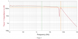
Again, reposting some of the impedance charts placing the Shure M78 on the VNA:
That's a mono cart. I wonder if the 50 kHz notch is not leakage inductance and the cable/input capacitance. F is too high to be the coil inductance.
- Home
- Source & Line
- Analogue Source
- Moving-Magnet Head Amp - without RIAA