Do not they generate a lot of wideband noise?Shade is a parallel feedback across an output tube. Exactly as an amp on an opamp in inverting connection.
SKIPPED
Edit: I forgot to add that output pentode must have well regulated screen grid supply. I use particularly VR tubes that glow nice and are more temperature stable than Zener diodes. Like this one: NOS NIB SG3S gas discharge voltage regulator tube 105V - eBay (item 180512428968 end time Jun-01-10 13:30:31 PDT)
Alex
P.S.Hello from tiasur graduate of 1984...
I wonder if a good portion of that is the fact you are using an output transformer with each version. Most transistor amps not requiring it...
Which are you suggesting; that the DC biased OPT is responsible for the 2f-dominant overtone signature, or that it's responsible for the overall sound? That's something to look at for sure.
I do need to look into it a bit more, because I can't see how the IGBT nonlinearity could contribute as much f2 as the vacuum tube, with the 200R degeneration in the source circuit.
Maybe it's the nonlinearity of the driver, and the 6L6 was adding the f3 in the tube case... I should examine the driver current waveform.
I should probably start a thread in the SS forum also; it's the similarity of SS to tube operation in this circuit that intrigues me.
Do not they generate a lot of wideband noise?
Alex
P.S.Hello from tiasur graduate of 1984...
Did they teach you in ТИАСУР that any conductor generates a wideband noise?
The question is not about a noise, but about S/N ratio. A noise that generate Zeners or cold cathode VR tubes connected to screen grids add negligible amount of noises to already existing ones.
I should probably start a thread in the SS forum also; it's the similarity of SS to tube operation in this circuit that intrigues me.
It is rather for Papaslab forum...
Last edited:
Do not they generate a lot of wideband noise?
Gas discharge tubes of all sorts do indeed generate noise. However, the quality of that noise is not nearly as distrubing as Zener diode noise, which is a reverse current through a PN junction. This is why Zeners need large bypass capacitors.
The gas discharge VTs I've used as voltage references for active regulators are quiet.
Re #119 Schadeode:
That was smart wiring C1 as an ultrapath.
High impedance at Q1's drain makes all the
power noise B+ common mode, so it can be
rejected.
Would PSRR have been even better with R3
upgraded to CCS?
That was smart wiring C1 as an ultrapath.
High impedance at Q1's drain makes all the
power noise B+ common mode, so it can be
rejected.
Would PSRR have been even better with R3
upgraded to CCS?
Last edited:
Re #119 Schadeode:
That was smart wiring C1 as an ultrapath.
High impedance at Q1's drain makes all the
power noise B+ common mode, so it can be
rejected.
Would PSRR have been even better with R3
upgraded to CCS?
Great minds... I'm going to experiment with a CCS next. Mainly to make the amp DC stable, but it can't hurt the already excellent PSRR. A cascode V/I converter is also in the works, but maybe for a "real' amp build.
Cheers,
Michael
Here was my version, with "Capacitive Schade" that is in parallel with non-linear intrinsic capacitances and shunt them.

Schade or not?
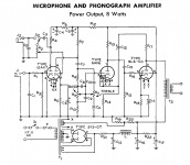
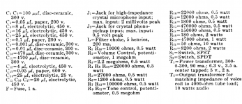
I am not suggesting the attached schematic 😱(from the RCA handbook # 20) is the latest and greatest, its highly likely just the opposite.
1) However I wonder if there is merit in having the feedback connection attached to the cathode of the driver tube instead of to the anode. It adds another capacitor in the path but are there advantages offsetting it? Perhaps it is something that may work better in (or improve) the Schadeode design?
2) Can this feedback still be regarded as a Schade feedback or is it something else?
3) I noticed the filaments sitting at something like 60VDC above ground and suspect the RCA engineers have done this for a reason. Is this to extend the life of the tube or is it for another reason (cathode - filament diode action perhaps?) Don't know and am interested in finding out.
As mentioned before in another posting: Although the 6AV6 is not identical to 1/2 of the 12AX7 (diodes and lower anode disspation) the curves are identical to 1/2 12AX7 and it can be replaced by 1/2 of the 12AX7. So one can leave the microphone section away and have an amplifier with (dare I to say it) tone control and approx 200mV sensitivity. Or one can leave the tone control altogether away.
I look forward to the thoughts.
AM
Attachments
Last edited:
I am not suggesting the attached schematic 😱(from the RCA handbook # 20) is the latest and greatest, its highly likely just the opposite.
1) However I wonder if there is merit in having the feedback connection attached to the cathode of the driver tube instead of to the anode. It adds another capacitor in the path but are there advantages offsetting it? Perhaps it is something that may work better in (or improve) the Schadeode design?
2) Can this feedback still be regarded as a Schade feedback or is it something else?
3) I noticed the filaments sitting at something like 60VDC above ground and suspect the RCA engineers have done this for a reason. Is this to extend the life of the tube or is it for another reason (cathode - filament diode action perhaps?) Don't know and am interested in finding out.
As mentioned before in another posting: Although the 6AV6 is not identical to 1/2 of the 12AX7 (diodes and lower anode disspation) the curves are identical to 1/2 12AX7 and it can be replaced by 1/2 of the 12AX7. So one can leave the microphone section away and have an amplifier with (dare I to say it) tone control and approx 200mV sensitivity. Or one can leave the tone control altogether away.
I look forward to the thoughts.
AM
1. Schade is parallel feedback by voltage; this one is serial feedback by voltage. Schade requires more current from driver, this one requires more voltage to drive driver. Schade decreases input impedance, this one increases it. This one adds substraction error, Schade does not. Schade shunts Miller capacitance, this one does not.
2.No
3. Hum reduction
PS: speaking for the amp from RCA book, go for it!
Last edited:
Feedback loop around 2 stages with 2 RC poles?
Maybe, maybe not... I really think Schade was
tryin' to emulate a triode's intrinsic local FB.
And that implies as little phase shift as possible.
I don't see a problem Schade FB to the cathode.
ARC ST70 does exactly that... But its only single
stage, single pole (is an OPT considered single?),
local feedback...
Schade's circuit certainly used a transformer...
Refinement we found convenient to tack on later.
Portion of Plate voltage fed back Grid to Cathode.
There's lots of ways to skin this cat...
Maybe others had done similar before, but Schade
proved how and why it should transform pentode
curves to triode.
Maybe, maybe not... I really think Schade was
tryin' to emulate a triode's intrinsic local FB.
And that implies as little phase shift as possible.
I don't see a problem Schade FB to the cathode.
ARC ST70 does exactly that... But its only single
stage, single pole (is an OPT considered single?),
local feedback...
Schade's circuit certainly used a transformer...
As orginally drawn by Schade? I sorta doubt...Schade shunts Miller capacitance
Refinement we found convenient to tack on later.
Portion of Plate voltage fed back Grid to Cathode.
There's lots of ways to skin this cat...
Maybe others had done similar before, but Schade
proved how and why it should transform pentode
curves to triode.
Last edited:
.... This one adds substraction error, Schade does not....
3. Hum reduction
PS: speaking for the amp from RCA book, go for it!
I am confused by the above remark (still relatively new to tube audio), does this mean that Schade works better (pentode is looking more like a triode with the advantages of a triode but with more power than the triode)?
Hum reduction: yes that is something that is very helpfull.
... go for it: in your opinion would this a better design than the RH807 (1/2 12AT7 + 807 with Schade feedback) It would be relatively easy to change, same chassis layout just change of driver tube.
AM
Speaking of "Works better", there are many ways to skin the cat, and definition of "better" vary. But I would never use neither 12AT7, nor 807 for SE amp. Especially 12AT7 loaded on low input resistance of an output stage with parallel feedback.
"substraction error"
The input to the driver tube is defined as the grid to cathode voltage, so moving the cathode V should be just as good as moving the grid V. Afterall, global neg. fdbk has used the cathode insertion mode successfully for an "eternity".
Since tubes naturally work best with high load impedances, the Schade technique is actually somewhat awkward, since it lowers driver input Z. Putting the feedback to the driver cathode instead raises the input Z, but requires more voltage gain then (which tubes are good at) and is a little trickier stability-wise across two gain stages (but more effective with the consequent higher loop gain, and certainly manageable without an xfmr in the local loop, like Schade's original setup had).
For Schade, the driver either needs a pentode with plenty of cathode degeneration to linearize it's V to I transfer, or a triode with lots of cathode degeneration to raise the output Z, or a series loading resistor to the output grid to linearize it's loading. These all throw gain away too. No clear winner.
The two schemes likely have somewhat different distortion profiles, which RCA (the handbook circuit) may have taken advantage of to tailor the final result by using some of both. Another unseen factor, with either version, is the slight variation of diffl. stage gains by means of common mode feedbacks altering the common mode stage biasing dynamically (unless CCS'd tails).
Some attention to PSRR is called for with either approach since the feedback source is B+ referenced, and the feedback insertion is often ground referenced. Some clever fixes possible with bypass caps or a pentode pre-amp.
Last edited:
" Another unseen factor, with either version, is the slight variation of diffl. stage gains by means of common mode feedbacks altering the common mode stage biasing dynamically (unless CCS'd tails).
I've addressed this issue by Concertina using a "free" triode from a combined input tube.
Triodes like high load impedance, but pentodes work fine when directly loaded by the low impedance (5K-10K ohms effective) of the feedback networkSince tubes naturally work best with high load impedances, the Schade technique is actually somewhat awkward, since it lowers driver input Z.
Not much gain is needed when using current mode feedback The input is a voltage-to-current converter. You only need to output the grid swing of the pentode you're driving. 2VRMS input to 20-30VRMS at the grid. Most pentodes with decent gm need cathode degeneration to keep from being too sensitive in the dozen or so design cases I've worked. Sharp cutoff tubes are generally pretty linear to begin with in a certain current range.For Schade, the driver either needs a pentode with plenty of cathode degeneration to linearize it's V to I transfer, or a triode with lots of cathode degeneration to raise the output Z, or a series loading resistor to the output grid to linearize it's loading. These all throw gain away too. No clear winner.
Using Schade feedback is no more sensitive to the power supply than a triode of equivalent plate resistance. The low effective Rp decreases the inherent PSRR by a couple of db. It's a factor of Zpri/(Rp+Zpri) where Zp is usually larger than Rp to begin with so you only get this factor a little closer to 1 by reducing Rp. Cancellation schemes can work well, as can active ripple reduction as in the Millett red board amp. Or a couple of big chokes and caps...Some attention to PSRR is called for with either approach since the feedback source is B+ referenced, and the feedback insertion is often ground referenced. Some clever fixes possible with bypass caps or a pentode pre-amp.
......
Maybe others had done similar before, but Schade
proved how and why it should transform pentode
curves to triode.
Thanks to all for their replies, much appreciated.
It is not yet clear to me if the feedback from the plate to the cathode of the driver results in the pentode having triode like curves. Perhaps someone can enlighten me on this one.
AM
1) I wonder if there is merit in having the feedback connection attached to the cathode of the driver tube instead of to the anode. It adds another capacitor in the path but are there advantages offsetting it? Perhaps it is something that may work better in (or improve) the Schadeode design?
While not Schade I suspect it works extremely well as it is identical to KYWs ideas - which he explains:
Using two stages for feedback (driver + output) allows a very low output impedance to drive the OPT, therefore greatly reducing distortions in it.
These two stages also have some self cancellation of distortion (IIRC) so the feedback loop is not working to hard - so maybe only a tiny bit of THD will be moved up the harmonic scale - perhaps to the 4th?
I'm not sure if miller capacitance is such an issue for driving pentodes but as the output tube is wired as a pentode you do get the easy drive, any miller capacitance can be I think ignored due to a decent current run through the driver (and the feedback loop).
So my take on this is:
1) Low drive impedance improves OPT performance
2) Max feedback path len is two stage driver-output tube.
3) Suits triode drivers (any drivers in fact)
For me this represents the easiest way to upgrade a global feedback loop SE to one that should sound the best it can without changing to schade, and perhaps better than schade if the impedance to the OPT can be lower than that method and of course it linearises the driver tube too.
Cancellation schemes can work well, as can active ripple reduction as in the Millett red board amp. Or a couple of big chokes and caps...
I like the idea of active ripple reduction - as this implies ripples caused by load will also be cancelled. I'll have to find the Millet read board schematic to see how it's done on that.
I like the idea of active ripple reduction - as this implies ripples caused by load will also be cancelled. I'll have to find the Millet read board schematic to see how it's done on that.
Perhaps you want to take a look at the other thread that I started on maximum allowable ripple http://www.diyaudio.com/forums/tube...max-allowable-reasonable-ripple-se-amp-3.html
AM
Thanks to all for their replies, much appreciated.
It is not yet clear to me if the feedback from the plate to the cathode of the driver results in the pentode having triode like curves. Perhaps someone can enlighten me on this one.
AM
Voltage feedback to: grid-to-cathode. Other than concern for phase,
why should it matter to Schade transform which end gets feedback?
- Status
- Not open for further replies.
- Home
- Amplifiers
- Tubes / Valves
- Most linear triode-strapped pentode