right now 25Vdc rails , but count on regular FW format - Donut with 2x 18Vac secs.
that resulting in some 22V5dc to 23Vdc rails
of course , few volts more couldn't do any harm 🙂
that resulting in some 22V5dc to 23Vdc rails
of course , few volts more couldn't do any harm 🙂
ZM, how are the two bias -3.5 and -4.1 made and adjusted?
I still wonder the function of the optocoupler. pin 4 3 is normally open and closed when the current through pin 1 2 ? So is this for protection or bias stability? Does the circuit work without optocoupler?
I still wonder the function of the optocoupler. pin 4 3 is normally open and closed when the current through pin 1 2 ? So is this for protection or bias stability? Does the circuit work without optocoupler?
didn't I pointed you before to my post in M2 thread , where I (little clumsy) explained how optocoupler thingie works ?
will this attachment help ?
anyway - back to M2 (find schematic , they are everywhere , as is deserved)
LED part of optocoupler is fed from (across) source resistors
say that current through source resistors is rising - opto LED is conducting more current , thus shining (whatever that means ) stronger
that shine is directed at paired bjt , where more shine is resulting in lower internal resistance of bjt itself ; it is connected between gates of upper and lower mosfet;
each gate is connected with , say , 47K to adjacent rail , so two 47K resistors and bjt in between are forming bridge between rails , and current through that bridge is - look back - governed by LED shine
so , back again , current through source resistors is rising , so voltage across them ; LED shines more , opening BJT
current through both 47K resistors is rising , thus voltage across them increasing ...... result is - two gates squeezing together , thus closing mosfets
so , current thrugh source resistors is decreasing , led is shining less , closing bjt .... current through 47K resistors decreasing , so is voltage across them ........ moving gates away of each other ....... opening mosfets ........ and here we go again
entire mechanismus explained here is somewhat exaggerated , things are much tinier and in equilibrium
now - Babelfish M25 is different from M2 in one tiny detail - there are no source resistors at mosfets , so their role are taken by current sensing chips in rails - current is rising , resulting voltage at IC is rising ;
voltages of two Hall chips are summed and taken to optocoupler , working pretty mach same as in M2
did I forgot something ?
oh yes ....... Ugs of SIT and mosfet , for same current , is not the same ; to put sources on proper voltage level , one just need to elevate/move gates somewhere from zero potential and that's easy - making those two "47K" resistors unequal
so - optothingy is taking care of (voltage ) distance between gates , while values of these two "47K" resistors are taking care where gates are gonna be , thus sources too ....... simply because sources always tend to follow gates
🙂
Attachments
Last edited:
Thank you ZM, I will read up the attached file before asking another.
Good night now, if you are done today's listening 🙂
Good night now, if you are done today's listening 🙂
Hi ZM can you in general terms describe the difference ( not technical -but sound 🙂 ) between Babelfish M25/SissySIT.
I currently have two types of speakers at home traditional inneffective 2way (86-87db) and effective Altec A5s and Altec 604-8g. The Altecs, although they are in the 98-100db range and can be used with 6-8W SE amps, like more for movies, prog, rock and large orchestra ( 20-40 watts eg PP EL34 and F6).
I currently have two types of speakers at home traditional inneffective 2way (86-87db) and effective Altec A5s and Altec 604-8g. The Altecs, although they are in the 98-100db range and can be used with 6-8W SE amps, like more for movies, prog, rock and large orchestra ( 20-40 watts eg PP EL34 and F6).
Last edited:
I could say that these are two different tools for different tasks
one of my guys asked me the same question yesterday ; I told him : "while you're still having Dynaudio Contour 1.8 , Babelfish M25 will do the job ....... and if you pony up for those 10" Tannoys I told you about , SissySIT will be better "
I called PapaSIT amps like this :
DEFiSIT (so SIT-3) : Pleasure Device
SIT-2 :Orgasmotron
SIT-1 :Orgasmotron^2
while Babelfish M25 is simply Berserked M2
edit: these Altecs you have are simply no good ; send them to OPLDF , and care would be taken
Give me that PCB Might Man!
I tried THF51 into the battery biased DEFiSIT.
These wild horses insist Vgs of -0.3V and -1.1V respectively. Ha ha..
I managed to bias them and am listening to them. I had to switch the polarity of CCS circuit.
Even these horses can be used in your circuit? I hope so.
If you know of a quiet bias supply that can replace batteries, please give me tip. 🙁🙁🙁 Of course until I can use some nice PCB of yours 🙂🙂
Attachments

Last edited:
....
These wild horses insist Vgs of -0.3V and -1.1V respectively. Ha ha.. ......
you mean - difference between gates , one channel 0V3 and other 1V1 ?
to be more specific , just measure Vgs of each of them , and write here
example - both THF51-S I used in SissySIT prototype are having -3V40 for 2A Iq , while one IRFP9240 is 4V1 , second is 4V5
that means , in first channel , there is (4V1-3V4)= 0V5 window to squeeze optocoupler bjt in , while in second channell window is (4V5-3V4)=1V1
silly me , I didn't even selected those IRFP9240 ...
Last edited:
Left Ch. THF51 Vgs -0.33 IRFP9240 Vgs -4.5 @1.5A voltage at 100 ohm 4.18
Right Ch. THF51 Vgs -1.10 IRFP9240 Vgs -4.5 @1.5A voltage at 100 ohm 3.19
I feel that IRFP9240s are pretty consistent. I have a couple of THFs more ;-)
Right Ch. THF51 Vgs -1.10 IRFP9240 Vgs -4.5 @1.5A voltage at 100 ohm 3.19
I feel that IRFP9240s are pretty consistent. I have a couple of THFs more ;-)
OK , numbers don't lie ....... but how's that , just -0V33 and -1V1 , for THF ??
I didn't measured them at other voltages/currents other than those interesting to me
so these are values for 15V of Uds and Iq 1A5 ? , where (just) 15V is obviously dominant
conclusion - for any selection , same must be done on intended rail voltage and intended Iq
logical , taking in account their resistive character
Yes 15V of Uds and Iq 1A5. THese number I can make with those pots.. 😀😀
I am throwing in other THFs.. I will get back to you.
So, am I one of that 250 guys who can have your PCB?
I am throwing in other THFs.. I will get back to you.
So, am I one of that 250 guys who can have your PCB?

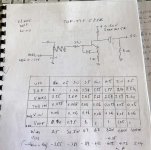
table handy to have everywhere
sorry , dunno who originally made it
edit: as I understand it , to Vbias written in table , you need to add voltage sag across 1R in source , to have effective Ugs
editedit: oh , yes , there is , in lowest row
sorry , dunno who originally made it
edit: as I understand it , to Vbias written in table , you need to add voltage sag across 1R in source , to have effective Ugs
editedit: oh , yes , there is , in lowest row
Attachments
Last edited:
I appreciate that ...
If Official Court Jester calls me funny. I AM funny !! 😀😀
This DEFiSIT is different.. Everybody needs to have a taste!. 🙂
If Official Court Jester calls me funny. I AM funny !! 😀😀
This DEFiSIT is different.. Everybody needs to have a taste!. 🙂
Thanks for the comments. I already have an Orgasmotron in my 300b monoblocks ( WE91 variants ) so Berserk is probably more for me 😉
Would not send my baad Altecs even to my worst enemy. Will lock them up in my cellar to keep sensitive audiophiles and innocent bystanders out of harms way 😀
Would not send my baad Altecs even to my worst enemy. Will lock them up in my cellar to keep sensitive audiophiles and innocent bystanders out of harms way 😀
I could say that these are two different tools for different tasks
one of my guys asked me the same question yesterday ; I told him : "while you're still having Dynaudio Contour 1.8 , Babelfish M25 will do the job ....... and if you pony up for those 10" Tannoys I told you about , SissySIT will be better "
I called PapaSIT amps like this :
DEFiSIT (so SIT-3) : Pleasure Device
SIT-2 :Orgasmotron
SIT-1 :Orgasmotron^2
while Babelfish M25 is simply Berserked M2
edit: these Altecs you have are simply no good ; send them to OPLDF , and care would be taken
OK then , let's say that SissySIT is WE91 Berserked
🙂
though , it's no good always opting for best or just better , sometimes right amount of romance and imperfection is perfect recipe for enjoyment

(not to mention how tube glow is ........... tube glow)
🙂
though , it's no good always opting for best or just better , sometimes right amount of romance and imperfection is perfect recipe for enjoyment
(not to mention how tube glow is ........... tube glow)
- Home
- Amplifiers
- Pass Labs
- Most Greedy Boy, of them all... or (there is no) DEFiSIT of Papa's Koans