1. which buffer - having 5R Rout?
yes, Rdc of windings is having some influence on Rout
2.term repeater is from telephony , ancient , and it is mostly xformer used for galvanic isolation , so no autoformer as here ; so - this is not repeater
I believe you don't need compensation cell for autoformer , but one can be sure only after observing voltage transfer in freq. domain and square waves shape
1. which buffer - having 5R Rout?
yes, Rdc of windings is having some influence on Rout
2.term repeater is from telephony , ancient , and it is mostly xformer used for galvanic isolation , so no autoformer as here ; so - this is not repeater
I believe you don't need compensation cell for autoformer , but one can be sure only after observing voltage transfer in freq. domain and square waves shape
A have a simple BJT emitterfollower...I have tried JFET follower, but they dont go so low...
Ok, so the driving part of the trafos Rdc is perhaps transformed with ratio and the rest is direct in series with output?
The Rdc is: 9R2, 9R2, 9R5 and 9R5.
If the first 9R2 is transformed with the buffer output the calcualtion is like this:
1:4=((5R+9R2)x16)+(9R2+9R5+9R5)=255R
1:8=((5R+9R2)x64)+(9R2+9R5+9R5)=937R
The first is close...the second at bit high....
Last edited:
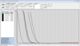
Hi cwtim, please switch in your curvetracer picture from the SK180 the "load conditions" button for me so I can see the real conditions you used.
The conditions shown are possible not the ones necessary for a measurement.
Please for me, I want to measure some parts from my basement too.....
😀😀
Thanks generg, please ignore the conditions you saw on the screenshot. My tracer was dead since a long time, and I only used the GUI client to open the data file for viewing the measurements before.
Those are Id_vs_Vgs curves with a fixed Vds of 20V. I had lots of 2SK180 at some point (mostly sold now), so those measurements were just a quick way to do coarse Vp matching.
I felt funny last few nights

Because Mighty Zen Mod cannot comment on his own posts, I'll do the honours (we spell it with a 'u' in Canada - honors/honours)
Fugly! Super Fulgy and Fugly is for Sissies!

Thanks generg, please ignore the conditions you saw on the screenshot. My tracer was dead since a long time, and I only used the GUI client to open the data file for viewing the measurements before.
Those are Id_vs_Vgs curves with a fixed Vds of 20V. I had lots of 2SK180 at some point (mostly sold now), so those measurements were just a quick way to do coarse Vp matching.
Thank you cwtim01!
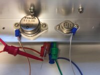
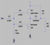
The DEFiSIT output stage works 😀, and it's fun to watch as things just adjust themselves automatically to stablize, and no bias circuit is required (OK, there is still a 100k resistor for the Vgs, plus 2 gate stopper resistors)
I use 2SK180D+IRF9240, put them across a -48V single ended power supply, and the bias is mostly defined by the IRF9240, while the Vds across the 2SK180D will change to match the current of the IRF9240.
The IRF9240 gives Id of 1.3A @Vgs=-3.9V, and at that Vgs the 2SK180D needs about 27V Vds to give 1.3A, leaving 21V to the IRF9240, hence output cap is definitely required.
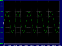
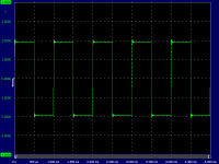
The sine output looks pretty clean, but I got some ringing with square wave, probably the 330R gate stoppers needs to be higher.
I use 2SK180D+IRF9240, put them across a -48V single ended power supply, and the bias is mostly defined by the IRF9240, while the Vds across the 2SK180D will change to match the current of the IRF9240.
The IRF9240 gives Id of 1.3A @Vgs=-3.9V, and at that Vgs the 2SK180D needs about 27V Vds to give 1.3A, leaving 21V to the IRF9240, hence output cap is definitely required.
The sine output looks pretty clean, but I got some ringing with square wave, probably the 330R gate stoppers needs to be higher.
Attachments
Last edited:
Congratulations!
I hope I can follow you in some time.
I too sold all my SK180 besides one. Left are only SK182 and the THF51.
But these are probably not in the right range.
I hope I can follow you in some time.
I too sold all my SK180 besides one. Left are only SK182 and the THF51.
But these are probably not in the right range.
I believe the best would be those 2SK180D that gives 1.3A @-4V Vgs and 23V Vds, matching well the IRF9240, and consume less heat.
I had a lot in that range before, but all sold, so can only use what remains.
I had a lot in that range before, but all sold, so can only use what remains.

I believe the best would be those 2SK180D that gives 1.3A @-4V Vgs and 23V Vds, matching well the IRF9240, and consume less heat.
I had a lot in that range before, but all sold, so can only use what remains.
saw this
SIT FET 2SK180 (C???)
so all Japanese DIYaudio fans are possible happy.......😀😀😀
The higher voltage ones are usable, and there are P ch mosfets with
comparable voltages. The lower ones, not so easy, but that doesn't
mean there are no solutions.
comparable voltages. The lower ones, not so easy, but that doesn't
mean there are no solutions.
it seems that the two THF51 in the middle are usable.
I estimate 3-3.2V @1.5A.
It seems you used a Vds of 16V for those measurements, and |Vgs| to give 1.5A will increase when you raise Vds to 20-ish range. For the 2SK180 I used, raising Vds by 7V actually changed the Vgs by 0.7V.
I think your THF51s will match well with 9240.
Yes the problem was that the Vgs in the curve tracer is stolen from the available max. Voltage of the device.
So the upper range of the curves got another slope than the beginning.
Reducing from 20 to 16V made the slope more equal.
I will drive the circuit with 35V, so I thought 16V for the SIT is near the half.
:--))
So the upper range of the curves got another slope than the beginning.
Reducing from 20 to 16V made the slope more equal.
I will drive the circuit with 35V, so I thought 16V for the SIT is near the half.
:--))
Who is the vendor?thf-51s still available from Pass approved vendor...
I will drive the circuit with 35V, so I thought 16V for the SIT is near the half.
In that case the 2 devices with higher Vgs are best.
But then, there is a way described here, which overcomes the differences and offer much more freedom.
By the way, when my Lockyz was still alive, I often controlled the Vgs via a 9V battery and 10k pot, this will leave much more voltage headroom for the measurements.
- Home
- Amplifiers
- Pass Labs
- Most Greedy Boy, of them all... or (there is no) DEFiSIT of Papa's Koans