I definitely think that 0.25 and 0.5 are realistic values for a one pair versus two pair comparison.
,
I don't really agree at all.
I have an amp I am listening to right now that has 3 pairs of output mosfets with no source resistors. Is Patrick going to say he has resistors that have negative resistance.
The problem I have with this sought of discussion is that, there are many ways to skin a cat, and it's wrong to present one idea as gospel, without presenting the other alternatives.
If Patrick had of presented the result of increasing source resistance vs not increasing source resistance, and the result of increasing total bias vs not increasing total bias, then it informs everyone.
There are lot of noobs here including myself, it's very easy for the wrong information to be spread, when someone with just a little bit of understanding but with a narrow minded point of view won't explore all the alternatives and what one is likely to implement in a diy amp.
I have never increased source resistance with increasing pairs of mosfets. I can understand why some people or manufacturers might though and even in that situation they don't increase directly with the number of pairs of mosfets.
I have never increased source resistance with increasing pairs of mosfets. I can understand why some people or manufacturers might though and even in that situation they don't increase directly with the number of pairs of mosfets.
Me neither, but I could understand why you may want of reduce them for just a single pair.
Me neither, but I could understand why you may want of reduce them for just a single pair.
Yes but you can't reduce resistance below 0 if you are already at 0 with 2 or 3 pairs
Yes but you can't reduce resistance below 0 if you are already at 0 with 2 or 3 pairs
I'm not sure that is a very common scenario for many builders. Even less common than running single pairs with 0.1 to 0.15R source resistors, which is what I think Patrick was saying at one point.
I'm not sure that is a very common scenario for many builders. Even less common than running single pairs with 0.1 to 0.15R source resistors, which is what I think Patrick was saying at one point.
No it's not common, but it is a real possibility, and it destroys the argument/defence made by Patrick, of him saying he doesn't need source resistors on a single pair, cause I can do the same thing with multiple pairs with no source resistors (with the right devices and matching).
Anyway I appreciate everyone's input (including Patrick). 🙂
trick is that Rs can be part of biasing mechanismus , taking care of temp. stability
and also Rs can be part of THD spectra shaping
so , speaking of Rs value , without placing it in broader context is fluffing in the wind
btw. , my is always smaller than yours ...... but - it's always mad as a hatter

and also Rs can be part of THD spectra shaping
so , speaking of Rs value , without placing it in broader context is fluffing in the wind
btw. , my is always smaller than yours ...... but - it's always mad as a hatter
trick is that Rs can be part of biasing mechanismus , taking care of temp. stability
and also Rs can be part of THD spectra shaping
so , speaking of Rs value , without placing it in broader context is fluffing in the wind
btw. , my is always smaller than yours ...... but - it's always mad as a hatter
Well said
Guess Iam going to find out...
OK, stupid question:
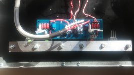
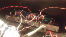
I have one channel up and running at .5V across the .47R source resistor.
Is this 1A bias (.5/.47) or is it 2A bias becasue I have doubled up the mosfets (I am using 2 pairs)? I understand the bias calculation (voltage across source R / source R) but when using 2 pairs do you multiply that by 2 to get bias?
With .5V across .47R I can hold my hand on the heatsink forever. I am using the 5U case.
Easily done.Thank you. Hoping to get to 2.5A for all class A down to 4ohms.
I suggest you check the maximum power dissipation (@Tc=25°C) of the devices you are using and limiting your actual dissipation to <<50% and preferably around 30%.
This leaves a margin in the SOA for the audio signal.
Compare to a ClassAB where the quiescent dissipation is ~5% of the cold maximum and the audio uses all of the remaining SOA.
This leaves a margin in the SOA for the audio signal.
Compare to a ClassAB where the quiescent dissipation is ~5% of the cold maximum and the audio uses all of the remaining SOA.
Andrew. there is no need for that. each device will have a lower dissipation then the original F5.
2.5A/2=1.25A pr device VS 1.3A for a standard single output pair F5
2.5A/2=1.25A pr device VS 1.3A for a standard single output pair F5
The check for Max:quiescent dissipation should not be omitted.
You have done a comparison based on a design where the check has already been carried out.
You have done a comparison based on a design where the check has already been carried out.
exactly my point. the test has already been carried out.
same rail voltage, just about the same current pr device. so what has changed?
there is ~30W dissipation pr device.
same rail voltage, just about the same current pr device. so what has changed?
there is ~30W dissipation pr device.
My suggestion stands vindicated.I suggest you check the maximum power dissipation (@Tc=25°C) of the devices you are using and limiting your actual dissipation to <<50% and preferably around 30%.
This leaves a margin in the SOA for the audio signal.
Compare to a ClassAB where the quiescent dissipation is ~5% of the cold maximum and the audio uses all of the remaining SOA.
One cannot ignore power dissipation/
Current and device temperatures alone, or together, are not the sole determining criteria.
Andrew:
Don't worry. I've only had two amplifiers catch on fire, I'll do my best to not let it happen again.
I'll keep an eye on the temp and make sure the bias stays stable. But .5v across the source resistors was not very hot. That's 2A bias. I can't imagine it's close to the limits. And 2A with 4 pairs is less dissipation per device than a stock F5. 2.5A is the same dissipation per device as a stock f5 and as long as the heatsink temps stay low enough I should be good. I wonder if the 1/2" aluminum bar stock I am using to "clamp" the mosfets down is helping to dissipate the heat? I know I have more even pressure this way.
Attachments
Last edited:
No it's the fact that the 5U case can easily dissipate 140W per channel without issue.I wonder if the 1/2" aluminum bar stock I am using to "clamp" the mosfets down is helping to dissipate the heat? I know I have more even pressure this way.
- Status
- Not open for further replies.
- Home
- Amplifiers
- Pass Labs
- Mosfets: Single pair vs multiple pair at same bias