Let’s use the F5 circuit as an example and make some further assumptions :
a) first stage bias = 7mA
b) 2nd stage bias 1.3A
c) Source resistor for second stage 0.47R
d) When using n MOSFETs in parallel, each MOSFET has its own source resistor = ( n x 0.47R )
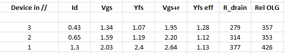
Using actual curve traced values from a 2SK1530 (as an example), the following values are obtained (see attached PNG file).
The drain current is (1.3A / n), where n is the no . of devices in parallel.
Vgs is the corresponding value for the MOSFET itself, i.e. at (1.3A / n).
Yfs is the transconductance at (1.3A / n).
Vgs+r is the Vgs voltage plus the voltage drop across the source resistors, the latter being (1.3A*0.47R =) 0.61V.
Yfs eff is the total transconductance of all parallel MOSFETs including source resistors degeneration.
R_drain is the resistor value to give Vgs+r at 7mA bias.
Rel OLG = R-drain x Yfs eff is an indictor to compare changes in open loop gain.
With the aforementioned assumptions, it does not appear to be beneficial to go for parallel devices.
That is already ignoring the corresponding increase in capacitances.
Patrick
a) first stage bias = 7mA
b) 2nd stage bias 1.3A
c) Source resistor for second stage 0.47R
d) When using n MOSFETs in parallel, each MOSFET has its own source resistor = ( n x 0.47R )
Using actual curve traced values from a 2SK1530 (as an example), the following values are obtained (see attached PNG file).
The drain current is (1.3A / n), where n is the no . of devices in parallel.
Vgs is the corresponding value for the MOSFET itself, i.e. at (1.3A / n).
Yfs is the transconductance at (1.3A / n).
Vgs+r is the Vgs voltage plus the voltage drop across the source resistors, the latter being (1.3A*0.47R =) 0.61V.
Yfs eff is the total transconductance of all parallel MOSFETs including source resistors degeneration.
R_drain is the resistor value to give Vgs+r at 7mA bias.
Rel OLG = R-drain x Yfs eff is an indictor to compare changes in open loop gain.
With the aforementioned assumptions, it does not appear to be beneficial to go for parallel devices.
That is already ignoring the corresponding increase in capacitances.
Patrick
Attachments
The main reason to increase pairs is to increase bias beyond 1.3A.
If you're not doing that then save those mosfets for another project.
If you're not doing that then save those mosfets for another project.
Let’s use the F5 circuit as an example and make some further assumptions :
a) first stage bias = 7mA
b) 2nd stage bias 1.3A
c) Source resistor for second stage 0.47R
d) When using n MOSFETs in parallel, each MOSFET has its own source resistor = ( n x 0.47R )
Using actual curve traced values from a 2SK1530 (as an example), the following values are obtained (see attached PNG file).
The drain current is (1.3A / n), where n is the no . of devices in parallel.
Vgs is the corresponding value for the MOSFET itself, i.e. at (1.3A / n).
Yfs is the transconductance at (1.3A / n).
Vgs+r is the Vgs voltage plus the voltage drop across the source resistors, the latter being (1.3A*0.47R =) 0.61V.
Yfs eff is the total transconductance of all parallel MOSFETs including source resistors degeneration.
R_drain is the resistor value to give Vgs+r at 7mA bias.
Rel OLG = R-drain x Yfs eff is an indictor to compare changes in open loop gain.
With the aforementioned assumptions, it does not appear to be beneficial to go for parallel devices.
That is already ignoring the corresponding increase in capacitances.
Patrick
EUVL:
Thanks. That's good info. I understand the benefit of parallel output devices is usually the ability to spread the heat and therefore allow higher bias...But I am already running a single pair at 1.8-2 amps. I am not sure how much more bias I will be able to achieve w/multiple pair. That's the real question...How much more bias will multiple pair allow me.
But I agree, I think that given the same bias....less mosfets might be better.
Which brings up a good question....why all the massively paralleled devices in a lot of commercial amps (even Pass Labs)? It costs more, it's more work, it requires matched devices. If the same bias (and temp) can be achieved with less pairs then why do we see so many amps with so many pairs of mosfets? Durability?
Hi Patrick,
With parallel devices the effective source resistance drops, for 1.3A total for example the drop is only 0.188V when three pairs are involved as the current is shared between three pairs (the effective current is 430mA as per your image, so with the same source resistor value the drop would be less).
What happens when you account for this?
The problem with using one fet (or pair) with boatloads of bias current is that it's difficult to get the heat from the one package to all the heatsink fin area needed to keep it from burning up.
With the aforementioned assumptions, it does not appear to be beneficial to go for parallel devices.
You are showing transconductance as proportional to bias current, but I seem
to recall that the relationship is a square root of bias current.
😎
Attachments
I have designed a few mosfet amplifiers using single, double, triple and quadruple pairs depending on power required.
I turn bias right down.
Then apply small sine wave to input. Monitor output with scope.
I slowly turn up bias until crossover distortion just goes.
This has always worked well for me and results in minimal bias current and good sound.
I turn bias right down.
Then apply small sine wave to input. Monitor output with scope.
I slowly turn up bias until crossover distortion just goes.
This has always worked well for me and results in minimal bias current and good sound.
EUVL:
Thanks. That's good info. I understand the benefit of parallel output devices is usually the ability to spread the heat and therefore allow higher bias...But I am already running a single pair at 1.8-2 amps. I am not sure how much more bias I will be able to achieve w/multiple pair. That's the real question...How much more bias will multiple pair allow me.
2A is a little on the high side for a single pair.
Total bias for multiple pairs will come down to your heatsink specs
Last edited:
I slowly turn up bias until crossover distortion just goes.
This has always worked well for me and results in minimal bias current and good sound.
Around here we usually go the opposite extreme. Hehehehe
What is the biggest heatsink I can afford and what is most bias I can run on that sucker. Hahahaha
2A is a little on the high side for a single pair.
Total bias for multiple pairs will down to your heatsink specs
Lateral mosfets should be around 100mA a pair.
For vertical mosfets you can get away with quite a bit less.
2A is a little on the high side for a single pair.
Total bias for multiple pairs will come down to your heatsink specs
it is the total amount of dissipation that matters. not the current alone.
it will depend on the rail voltage. running the outputs on the edge will give them a very short lifespan. heatsink capacity does also play a role.
baseplate thickness in regard to heatsink size can determine how many output devices needed to spread the heat across the intire surface.
a roule of thumb is, the heatsink can spread the heat at a radius of 10x the base thickness.
Lateral mosfets should be around 100mA a pair.
For vertical mosfets you can get away with quite a bit less.
100mA for a class A amp???????? we are not talking class A/B now.
Of course. Since we are talking about F5, it should be safe to assume we are talking about the range of 22V to 24V, in which case 2A is a little on the high side.it is the total amount of dissipation that matters. not the current alone.
it will depend on the rail voltage.
yes it is. i set my limit to 35W dissipation pr device to be on the safe side and a long lifespan of the devices.
You are showing transconductance as proportional to bias current, but I seem
to recall that the relationship is a square root of bias current.
😎
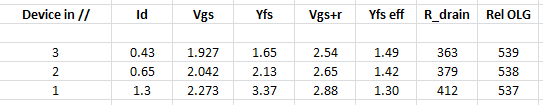
You are right.
There was a small bug in the derivation of Vgs & Yfs from curve traced data.
This is now corrected and double checked against measurements.
If you just consider paralleled Yfs, there is some gain in going parallel.
If you take R-source and R-drain into account, then they are pretty even.
And you get lower junction temperature, but pay the price with capacitances.
😉
Patrick
Attachments
Not really. Bandwidth is still over 1 MHz even with 3 pairsbut pay the price with capacitances.
😉
Patrick
Edit: Can't remember the exact bias level somewhere between 1.3A and 2.0A, it measured well over 1MHz on the oscilloscope.
Last edited:
You are right.
There was a small bug in the derivation of Vgs & Yfs from curve traced data.You're is now corrected and double checked against measurements.
If you just consider paralleled Yfs, there is some gain in going parallel.
If you take R-source and R-drain into account, then they are pretty even.
And you get lower junction temperature, but pay the price with capacitances.
😉
Patrick
Nope, the voltage drop for 470mOhm resistors is about 188mV when the bias current per pair is 430mA. Ohm's law. You're not accounting for that either.
I agree about capacitance though, it is a price. Not sure how a little cascode jfet can discharge few nF of gate capacitance. However seeing Nelson's commercial amps routinely paralleled 10 pairs, there's obviously another side to this story.
The bandwidth also depends on other things in the circuit.
I did not suggest that you would not get enough bandwidth.
But capacitances will increase proportionally to n, and need to be taken care of.
Patrick
I did not suggest that you would not get enough bandwidth.
But capacitances will increase proportionally to n, and need to be taken care of.
Patrick
Last edited:
What is the effect of greater capacitance? Rolled off highs? Less bandwidth?
I run 24v rails, 1.8a bias on a single pair in 90f degree weather all summer long. No AC where I live. Heatsinks are 50c with the 5U case. Summer here (seattle) has been brutally hot. They say Seattle is the new california.
Iam hoping to get 2.5a bias with 3 pairs and same case temp. That is the goal. I have 2 pieces of 1/2 aluminum bar I will clamp down the fets with for more even pressure and hopefully to provide som cooling to the back side of the fets.
Bias seems to be the single most important factor to this amplifiers sound. That's been my experience.
> Nope, the voltage drop for 470mOhm resistors is about 188mV when the bias current per pair is 430mA. Ohm's law.
Maybe I did not explain myself well enough in the original post or we have a language barrier.
I said that one of the assumptions was :
"d) When using n MOSFETs in parallel, each MOSFET has its own source resistor = ( n x 0.47R ) "
So in case of 433mA, n = 3, and R_source = 1.41R.
I consider this to be a fairer comparison than using R_source = 0.47 for n = 3.
Because then I can also argue that I can use R_source = 0.15 for a single device.
0.47R is not a holly number, but just a design parameter.
I have use anything from 0.1R to 1R, depending on the application.
In the F5X for example, R_source is 0.22R.
Patrick
Last edited:
- Status
- Not open for further replies.
- Home
- Amplifiers
- Pass Labs
- Mosfets: Single pair vs multiple pair at same bias