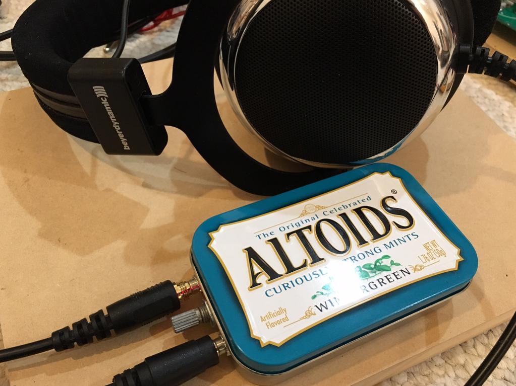
Thanks Hugh! It's surprisingly or shockingly good sounding. Never thought I could squeeze it all in the tin of mints format with connectors, jacks, volume pot, and batteries.
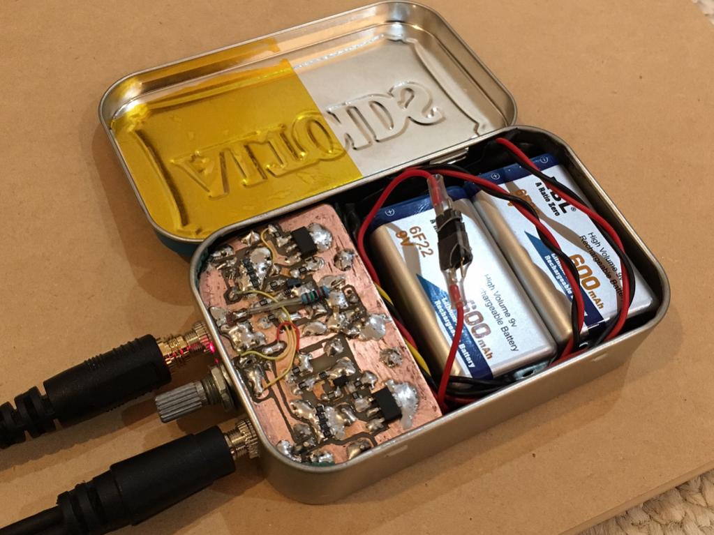

Ok, I took this baby on a 1.5hr bus ride and had plenty of juice. And the tunes sounded splendid in their class A glory! Did not get too hot either. Hopefully there is enough charge for the ride home. If so - I will declare this a success as it was designed with my daily commute in mind so needs circa 4hrs of batt life.
67mA for MOSFETs + 8mA for JFET = 75mA per channel x 2 channels = 150mA. 600mAr batteries should barely get me 4 hrs. 🙂
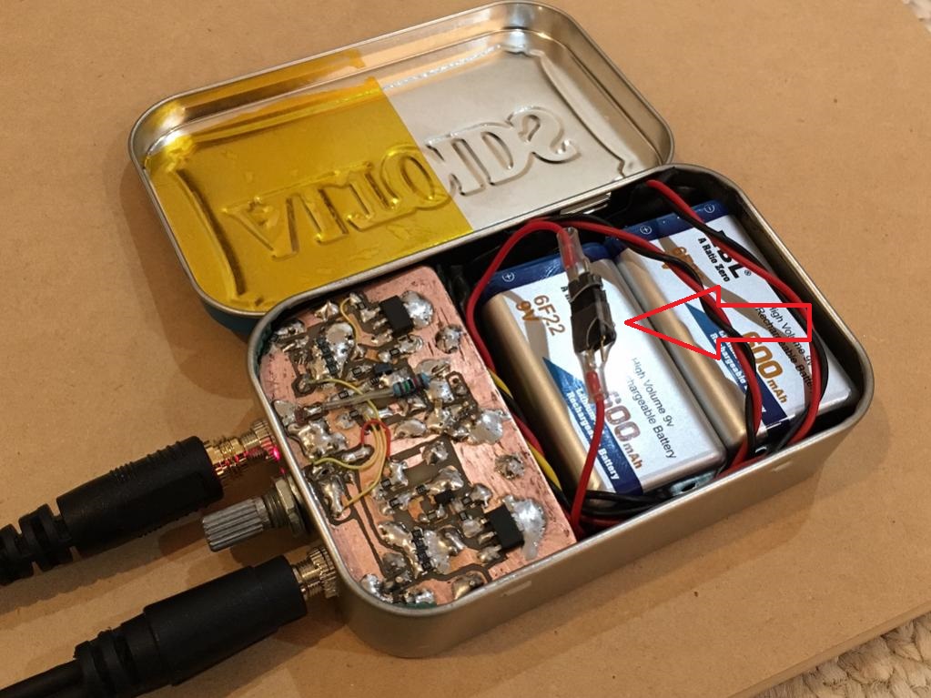
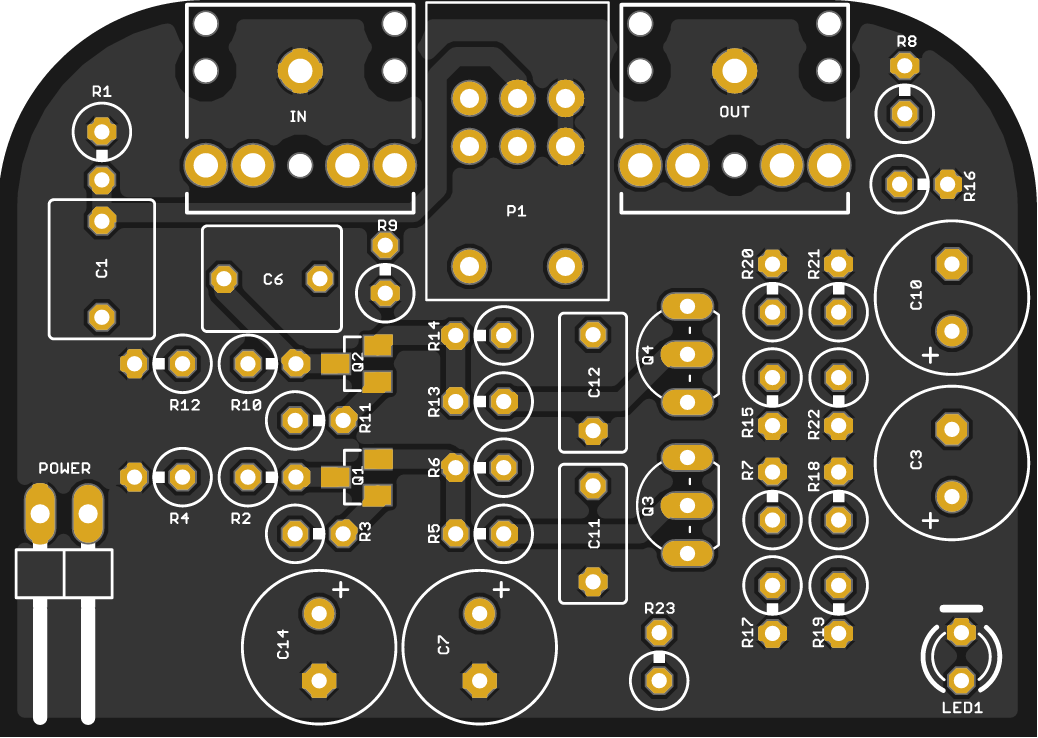
One more note, my implementation of the minimalist power switch worked out very well: the 2-pin header connector with only one pin live has two positions if you pull out and twist connector 180 deg you get on/off. Takes no space is very reliable and cannot be accidentally turned on/off like a toggle switch hanging out. I don't mind opening lid to turn on/off.
67mA for MOSFETs + 8mA for JFET = 75mA per channel x 2 channels = 150mA. 600mAr batteries should barely get me 4 hrs. 🙂
One more note, my implementation of the minimalist power switch worked out very well: the 2-pin header connector with only one pin live has two positions if you pull out and twist connector 180 deg you get on/off. Takes no space is very reliable and cannot be accidentally turned on/off like a toggle switch hanging out. I don't mind opening lid to turn on/off.
Attachments

Last edited:
Sim of this amp in HA thread:
http://www.diyaudio.com/forums/head...lass-headamp-without-heat-13.html#post4945515
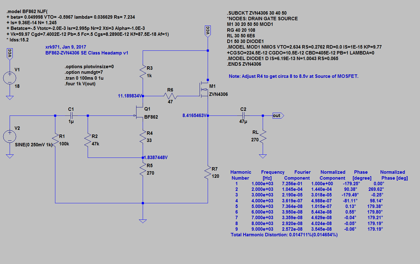
I figured out how to import 3rd party model to LTSpice.
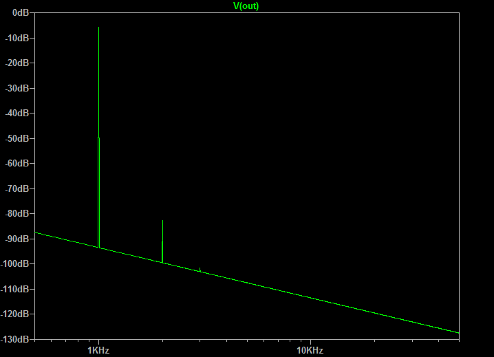
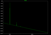
Nice FFT:
http://www.diyaudio.com/forums/head...lass-headamp-without-heat-13.html#post4945515
I figured out how to import 3rd party model to LTSpice.
Nice FFT:
Maybe is a time to complete the GW mk3 and compare the sound with other headamps you presented here.
BR Damir
BR Damir
Maybe is a time to complete the GW mk3 and compare the sound with other headamps you presented here.
BR Damir
I know, I know... I am still gathering parts for the BOM. I thought I had everything but turns out I am missing the 2N5485 so have those on order. Your amp has so many actives, it makes my head spin. Unlike these simple 2 transistor amps I have been making lately 🙂
I have J110, J310, can I sub that for 2N5485? Does it need to be rate for such high currents?
I had just ordered the DN2540 for the PSU already, and I have plenty of BC550/560's and BD139/140's and 2SK170BL's so should be set after this.
Last edited:
I know, I know... I am still gathering parts for the BOM. I thought I had everything but turns out I am missing the 2N5485 so have those on order. Your amp has so many actives, it makes my head spin. Unlike these simple 2 transistor amps I have been making lately 🙂
I have J110, J310, can I sub that for 2N5485? Does it need to be rate for such high currents?
I had just ordered the DN2540 for the PSU already, and I have plenty of BC550/560's and BD139/140's and 2SK170BL's so should be set after this.
J110 could be used, you need to find what source resistor will give about 8 to 10 mA of CCS current.
I am very interested to hear your listening opinion.
J110 could be used, you need to find what source resistor will give about 8 to 10 mA of CCS current.
I am very interested to hear your listening opinion.
I think J110 is only good for 2mA. J310 can give 10 mA with the right resistor. What is voltage across that JFET? 15v rail will need about 1.5k for 10 mA?
I think J110 is only good for 2mA. J310 can give 10 mA with the right resistor. What is voltage across that JFET? 15v rail will need about 1.5k for 10 mA?
No, L110 Idss is 10 mA min, but looking the graphs it looks it can be even 300 mA, so maybe is not good. J309 could be good one.
http://www.onsemi.com/pub_link/Collateral/J110-D.PDF
Or better try to get BF245C or even between BF245B you can find the ones with Idss higher of 10 mA.
What about 2SK170BL?
That is excellent low noise jfet with Idss between 6 and 12 mA and very low Vgs(off), pity to use it here in this position. Actually V version with Idss between 10 and 20 mA but still pity to use here.
If you have to much of this you can sell some to me if not fakes.
Ok, I took this baby on a 1.5hr bus ride and had plenty of juice. And the tunes sounded splendid in their class A glory! Did not get too hot either. Hopefully there is enough charge for the ride home. If so - I will declare this a success as it was designed with my daily commute in mind so needs circa 4hrs of batt life.
67mA for MOSFETs + 8mA for JFET = 75mA per channel x 2 channels = 150mA. 600mAr batteries should barely get me 4 hrs. 🙂
One more note, my implementation of the minimalist power switch worked out very well: the 2-pin header connector with only one pin live has two positions if you pull out and twist connector 180 deg you get on/off. Takes no space is very reliable and cannot be accidentally turned on/off like a toggle switch hanging out. I don't mind opening lid to turn on/off.
Just an update that in actual real world testing today, the batteries lasted both ways in my commute and still had juice to spare. So 4hrs operation is not a problem. Temperatures were not too hot and amp was just slightly warm to hold. Actually useful on a windy 21 deg F day here in DC. Very happy with the performance. Amp was absolutely solid with no loose connections or noise from walking during use.

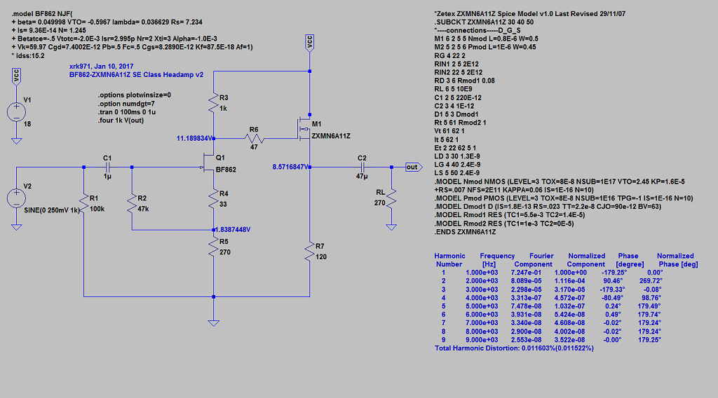
Same amp with ZXMN6A11Z
I just ran a simulation with a simple change to the output MOSFET to a ZXMN6A11Z and things improved a bit. THD went from 0.014% to 0.011%, plus the part is actually half the price and has a Rdson that is 1/3rd the value of the ZVM4306. The package is SOT-89-3 though so doesn't have a nice heat sink tab like the former. It does have a 4th little pin that mught remove some heat (claimed 1.4w) so might work. I have a set anyhow I can try. I am using the model from the manufacturer, Diodes Inc. here:
http://www.datasheetarchive.com.cn/files/diodes-inc/spice-model/1384.mod
Attachments
Last edited:
Fresh off the press. BDHM did a bang up job on a through hole (mostly) version!
http://www.diyaudio.com/forums/head...2-based-se-class-headamp-without-heat-15.html
http://www.diyaudio.com/forums/head...2-based-se-class-headamp-without-heat-15.html
Changing the device models and repeating the simulation is simply reporting the difference in the models of the devices.I just ran a simulation with a simple change to the output MOSFET to a ZXMN6A11Z and things improved a bit. THD went from 0.014% to 0.011%, plus the part is actually half the price and has a Rdson that is 1/3rd the value of the ZVM4306. The package is SOT-89-3 though so doesn't have a nice heat sink tab like the former. It does have a 4th little pin that mught remove some heat (claimed 1.4w) so might work. I have a set anyhow I can try. I am using the model from the manufacturer, Diodes Inc. here:
1384 - Datasheet Archive
There is a good chance both models are so severely inaccurate that the simulations are not realistic.
The simulations here are more than useful to assess the THD and particularly, the profile.
Short of building them, and X has built all of them and displayed them, with subjective comments, a careful simulation is helpful. The voltages are actually quite close.
I think this has been a terrific project for DIY, and it's built, it's simulated, and is working. Andrew, I really don't see the point of your post. Simulation is essential in all complex projects now, and the tools are improving all the time. Could you design an automobile these days without simulation tools? I always begin my new amps with a meticulous simulation and spend many days moving values around to watch where the operating points change.
I thank XRK971 for his sterling hard work - given freely to the forum.
Cheers,
Hugh
The point is that Xrk is comparing two FET models.
I am raising a concern that the models may be sufficiently inaccurate such that the sim may be reporting a prediction for a different harmonic content that may not happen in practice. The prediction is based on the model parameters and these are reputed to be quite variable in quality.
your example reported here
And I agree with you, the three or four altoid projects form a great and useful resource for any that want a ClassA headphone driver.
I have been following all his posts and receive them as they are intended.
I am raising a concern that the models may be sufficiently inaccurate such that the sim may be reporting a prediction for a different harmonic content that may not happen in practice. The prediction is based on the model parameters and these are reputed to be quite variable in quality.
your example reported here
is looking at changing operating points and passive values to see what they do to the predicted performance. That is a quite different investigation compared to swapping a FET model.I always begin my new amps with a meticulous simulation and spend many days moving values around to watch where the operating points change.
And I agree with you, the three or four altoid projects form a great and useful resource for any that want a ClassA headphone driver.
I have been following all his posts and receive them as they are intended.
Last edited:
- Home
- Amplifiers
- Headphone Systems
- MOSFET Source Follower Headamp