A little contemptuous, Juma?
We're a bit slow, perhaps, but have already refined one of your circuits sonically.......
HD
We're a bit slow, perhaps, but have already refined one of your circuits sonically.......
HD
Not at all. Sorry if you felt it that way. It was not my intention.A little contemptuous, Juma?...
I just thought that a day in a library can save weeks in a workshop...
Thank you for the articles Juma. I forgot about them but now are very pertinent to the subject at hand.
Etching in progress... I figured I would just make the amp board and use the input stage as the matching rig. This was hand drawn with just only a Sharpie marker and is missing a 100k input resistor which I can add with a through hole jumper resistor to GND. This is some old solution so is taking longer than usual 20min.

Attachments
Prasi,
This is a reasonable question because the matching is tiresome and time wasting.
The problem is that you have two, three, four or five devices with identical gate potential.
This means that because of the huge variance of BF862s - and indeed all jfets and quite a few mosfets too - you finish up with one identical Vgs from this one gate potential. The result is that one jfet will pass 6mA, another 10mA, and another 12mA, and the y(fs) - transconductance - will vary markedly from one jfet to the next.
This will introduce distortion, which does not sit well in my mind.
Another option is to use a small mosfet which passes large current and, if cooled well, will avoid these matching issues. The one I have in mind is the ZVN2110A which is typically ten times y(fs) (250mS) and rdson of 5R and up to 700mW in TO92. The Ciss is 75pf, which is OK in this role, and it will run from 20V, with max at 100V. With one device in the output stage, we do not need matching, and the N enhancement means the source is about 1.5V below the voltage of the gate.
Hmmm....... thimks..........
Hugh
That is interesting too and could mean a 2 transistor device? Would not two of them then be better to have as a CCS on the bottom? This was in fact what Easphyx proposed, only with two ZVN4306A, which can pass even more current (although cooling a TO92 with such power is impractical).
From "Tin of FETs" thread:

I like SOT23's in parallel though - they take care of the heatsinking issue and lend themselves to very compact layouts.
Yes X!
I am reading Juma's Borbely article too - I like the Fig 5 showing how to measure Idss, Vp and gm but the eBay gizmo is superior in use.
I went after a better ZVN and also found the 4306 which offers SOT223 and 3W. That would be ideal in the 'white follower' you presented.
I really can see nothing better; this would give complete transparency to the output stage of any HPA and I would direct couple it and run with 40mA.
HD
Electros. There are many; Nichicon,
Black Gate, Cerafine, Rubycon, Kendeil etc.
Matching.
Use same 18V
Set up a jig with 1k drain resistor, 10R source resistor to ground and a 220k direct from ground to gate.
Install BF862 and quickly measure voltage to ground.
You simply need three devices with identical drain to ground - around 8.5V.
You do not need a particular voltage; you want three identical voltages only. This process gives identical Vgs for 10ma drain current and identical dc gm. AC gm is slightly different but it is close enough.
These devices warm up under test. Ensure all start at same ambient temperature and read off the drain voltage within 4 seconds with a fast DMM like a Fluke.
HD
Hugh,
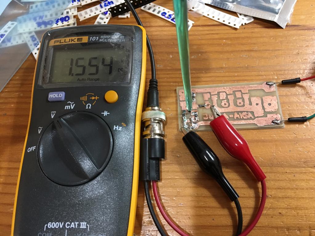
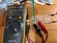
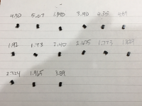
I set up the rig as described with 1k on Drain to 18v, 220k from Gate to GND, 10R from Source to GND, and measured at Drain pin relative to GND. I get voltages that are in 1.5v to 4v range - looks more like typical Vgs values rather than the circa 8.5v you are predicting. Did I do something wrong? I m using two 9v batteries in series so voltage is 19.5v. I think the particular BF862's I have need higher Source resistance to get the voltage up. I seem to remember running into his issue when making the preamp and changed Source resistor to 47R.
Here is jig with the JFET being pressed by a non conductive push stick.
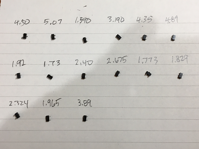
Here is what I measured with my remaining BF862 JFETs:
Attachments
Last edited:
Your measuring jig has to hold some conditions at some steady known values.
You need to hold current constant, or Vgs constant, to be able to compare devices.
I think you have described a source resistor and a Vds.
If the Idss is different then a different current passes through the resistor. This leads to a different Vgs and thus a different operating point.
Pick a few devices that end up very close to each other.
Measure the Idss and then compare these few at a suitable Rs to give the Vds you require.
Last edited:
I could replace the 1k with J310 and suitable R in CCS mode to get required 12mA. I think. 330R between S and GND with G tied GND should be close to getting me circa 12mA?
Yes X!
I am reading Juma's Borbely article too - I like the Fig 5 showing how to measure Idss, Vp and gm but the eBay gizmo is superior in use.
I went after a better ZVN and also found the 4306 which offers SOT223 and 3W. That would be ideal in the 'white follower' you presented.
I really can see nothing better; this would give complete transparency to the output stage of any HPA and I would direct couple it and run with 40mA.
HD
Hi Hugh,
What would a circuit with the outputs as ZVN4306GTA look like? Since it is not depletion mode it needs a bias source now. Usual zeners and JFET CCS's to set bias?
to my eyes, depletion Mosfet BSP129 is better choice
Interesting MOSFET but is 6ohm Rdson vs 330mOhm for ZVN4306 - which is 3W dissipation.
Good luck running 3A through SOT223 😀
Even 1W on SOT223 will burn your fingers badly without proper heatsink 😀
Even 1W on SOT223 will burn your fingers badly without proper heatsink 😀
I agree 3 Watts is a lot but it means a 100mA bias current is not a problem - solder onto a copper tab.
X,
I've had more time to consider it. I think we need to select for Idss, so connect gate AND source to ground, and then measure the voltage across the 1K, which is same position from drain to Vcc.
Then select on Idss, running the source followers devices with current at 2/3 Idss. If you select three at 12mA, run each at 8mA, same circuit as agreed.
The other mosfet circuit with the ZVN4306 could be run at a simple source follower, with gate stopper of 100R from the drain of the previous BF862 first stage.
I will do some sims on this both with passive resistor loading, and CCS.
Hugh
I agree 3 Watts is a lot but it means a 100mA bias current is not a problem - solder onto a copper tab.
Yes. But you are limited with package, do not trust marketing words. If ZVN4306 in SOT223 can do 3W, than BSP in SOT223 can do the same. With proper heatsink of course.
With 100mA bias and 10V across output Mosfet, what will be Rdson? Do you still think 330mOhm Rdson is THAT important?
Last edited:
X,
I've had more time to consider it. I think we need to select for Idss, so connect gate AND source to ground, and then measure the voltage across the 1K, which is same position from drain to Vcc.
Then select on Idss, running the source followers devices with current at 2/3 Idss. If you select three at 12mA, run each at 8mA, same circuit as agreed.
The other mosfet circuit with the ZVN4306 could be run at a simple source follower, with gate stopper of 100R from the drain of the previous BF862 first stage.
I will do some sims on this both with passive resistor loading, and CCS.
Hugh
Ok, I will remeasure based in Idss. I wonder if there will be any correlation to the drain-ground voltages I measured earlier.
New Circuit
I have reworked the original design to maintain the jfet sonic signature, give more peak to peak output from 18V rail, drive low Z cans, and reduce the distortion across the board.
I built this some years back and it sounds stunning. It needs a BF862 with Idss selected of 10mA, and a BD140. Phase shift at 20KHz is only 0.3 degree.
HD
Attachments
This is really nice Hugh. So many choices now! How can you beat 2 transistors? Your circuits are refreshingly simple and have only H2 and very low H3 which I really like. I would probably still make this as mostly SMT board with room for through hole BD140. If I heatsinked it well, what changes would be needed to get 50mA bias? And would that help SQ? Is this still a pure class A amp?
- Home
- Amplifiers
- Headphone Systems
- MOSFET Source Follower Headamp