Hi Mile, was this a FET preamp earlier ? The title says FET preamp though the devices are all bipolar .
Thanks.
Thanks.
Yes it is an old mistake, there was the complementary jfet SF3.1 and this is the complementary bjt. It simulated nicely, the bjt was lower distortion, well in the sims at least. On my list to build one day!!
Last edited:
There is many preamps... use this circuit.
Thanks apex ,always The Best.
You have Pcb And montage Plan for fet preamps?
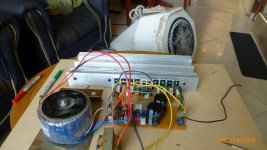
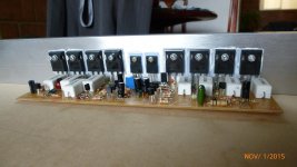
This is my project apex hv23 . In the first test , it worked well for 15 minutes with average volume when the 5 amp fuse on PSU -7 was burned , the heat sink was lukewarm. Why , if the fuse goes to the transformer?. 45-0-45 v ac 450w. thanks
Attachments
This is my project apex hv23 . In the first test , it worked well for 15 minutes with average volume when the 5 amp fuse on PSU -7 was burned , the heat sink was lukewarm. Why , if the fuse goes to the transformer?. 45-0-45 v ac 450w. thanks
Nice work, what is dc offset and bias measurements?
Nice work, what is dc offset and bias measurements?
dc offset: 8.9mv
bias: 23mA *+****-.
It is not the same measure in all resistors R47: 3 are 10.5 mv + - and the other 14.5mv
I replace the fuse and a 35mA BIAS works great . I filled my expectations , very satisfied. thank you very much to apexaudio and all for your post
What features should have the speaker , to have good sound with Apex hv23 amplifier. and how many watts. I think my speaker is very small. Thank you
Is this part to use in hv23 amplifier?sir apex,
what is the detail of this choke coil?
wire size,
core dia.
no.of turn.
hello mister Mile the proper bias adjustment for the Apex HV23 is about 10mV or can be a bit more ? I mean best bias settings 🙂
Regards
Juan
Regards
Juan
Attachments
Last edited:
Optimal ClassAB requires ~26mVre at the outputs, when Tj is @ ~27°C (~300K).
And rises in direct proportion to K temperature, i.e. Tj=330K requires ~(26*1.1)mVre
But that includes the internal re of the transistor.
D.Self gives a lot of data on this.
And rises in direct proportion to K temperature, i.e. Tj=330K requires ~(26*1.1)mVre
But that includes the internal re of the transistor.
D.Self gives a lot of data on this.
Last edited:
hello
I have a question mister Mile, does Q9,10 from Apex HV23 need to be installed to main heat sink always ?
Regards
Juan
I have a question mister Mile, does Q9,10 from Apex HV23 need to be installed to main heat sink always ?
Regards
Juan
hello
I have a question mister Mile, does Q9,10 from Apex HV23 need to be installed to main heat sink always ?
Regards
Juan
Yes Q9 and Q10 must be on main heatsink.
Regards
Yes Q9 and Q10 must be on main heatsink.
Regards
thanks mister Mile 🙂
Regards
Juan
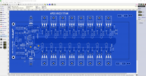
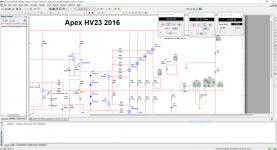
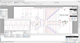
Hello guys I don't think I ever gonna build this but it does look interesting, I almost completed 🙂 yes I know is not practical just ideas "maybe too crazy" 🙄
That's very nice. 1000w? If it gets checked out and approved by others around here I would like to build it. Hexfets are cheap. 🙂
What's the ps rail voltage? Maybe high enough we just need to rectify wall AC and add caps (save a ton on the lack of a trafo)?

Last edited:
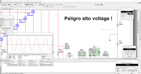
I simulated with 150V rails and I get before clipping 1600W I'm just having fun 😀 with this the correct rail value is 75V DC too dangerous to play with this rails voltages 🙄 but I have add two 330 resistors for the driver board 🙂
Attachments
Last edited:
clipping indicator not working on simulation
hello guys
I have a little problem with the clipping indicator circuit seem not to work on simulation, does "PRO" need to be connected in order to clipping indicator to work? I'm attaching the multisim 14 file and PDF
I most then making a mistake for sure, but I'm not sure what it is 🙁
Regards
Juan
hello guys
I have a little problem with the clipping indicator circuit seem not to work on simulation, does "PRO" need to be connected in order to clipping indicator to work? I'm attaching the multisim 14 file and PDF
I most then making a mistake for sure, but I'm not sure what it is 🙁
Regards
Juan
Attachments
Last edited:
hello guys
I have a little problem with the clipping indicator circuit seem not to work on simulation, does "PRO" need to be connected in order to clipping indicator to work? I'm attaching the multisim 14 file and PDF
I most then making a mistake for sure, but I'm not sure what it is 🙁
Regards
Juan
Hi Juan,
I think Mr. Miles is on holiday, when he comes back, i am sure he will reply.
reg
prasi
- Home
- Amplifiers
- Solid State
- MOSFET Amplifier IRFP240/IRFP9240