the irf240 does not have an emitter.................i measured the emitor resistor voltage, any solution?
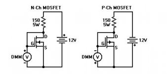
solution:- Take out all your FETs and select for equal Vgs at the operating current.For mosFET output stage it's variation in Vgs that leads to even bigger variations in Id and that shows when reading individual Vrs (voltage across the source resistor).
Am I wasting my time with unhelpful posts?and that variation in Vgs for paralleled mosFETs is why it is absolutely important that devices be selected for very close Vgs at the target operating current for the amplifier output stage.
bad luck
that is why i said:
after his:
he did not take us seariously;me mistaking and you correcting...
the irf240 does not have an emitter.
solution:- Take out all your FETs and select for equal Vgs at the operating current.Am I wasting my time with unhelpful posts?
that is why i said:
don't mention it...
after his:
hi apex sir ,
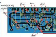
like this when i measured the emitor resistor voltage, any solution?
he did not take us seariously;me mistaking and you correcting...
guys i still have a problem with the 30mA bias current issue. in terms of voltage accross the source resistors (0.47ohms), is the voltage acccros them 14.1mV?
replace 470R trim-pot with 1k trim-pot and than adjust bias as you wish,or
http://www.diyaudio.com/forums/soli...mplifier-irfp240-irfp9240-67.html#post3228580
yesterday i did some mesurments at home with APEX HV23 at about 11,5Ohm resistor. it has given to me 45V/3,55A , 48V/4,05A and 51V/4,33A without clipping. at 53V there was 4,5A but clipping appeared. this all was at 1kHz frequency from signal-generator and lasted for about 15sec per measuring voltage/current. i did about ten this mesuraments so the amp was really taken to it´s maximum limits. it has got heated up but not so much more than it gets when it reaches it´s working temperature. it has only been left to find someone willing to share it´s loudspeakers with my amplifier to test it "live" and with music program instead tone-generator.
Last edited:
so in other words, 30-50mA is the range to bias if the trimpot is 1k? and also the voltage i intend to use is 44-0-44 ac. i know power will be lower than the expected but its worth the try.
not in my case because i have +/-75V supply. i can adjust it to a 100mA per pair but i don't have heatsinks to cool it down,also it sounds the same with 15 and 100mA bias so why to exaggerate.
i don't know how much power you will get with +/-63V supply,but it is to be expected about 200W/8R and 300W/4R load. let us know when you measure! 🙂
i don't know how much power you will get with +/-63V supply,but it is to be expected about 200W/8R and 300W/4R load. let us know when you measure! 🙂
44250, i need the bias proceedure. things like initial values of resistances before and other information that i may need in this area.


Shelah, you don't need fans with those huge heatsinks! 😀
It depends on how long it is switched on for and if the case has openings for airflow.
I used a similar setup in a pc case and after a couple of hours of high power I couldn't bear my hand on the pc case. So I fitted a couple of fans and it was fine after that.
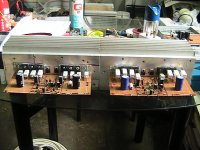
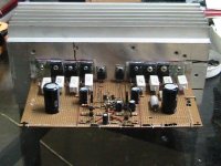
i present to you DIY apex HV23.
hardwork. good heatsink.
what purpose u made with vero board?
- Home
- Amplifiers
- Solid State
- MOSFET Amplifier IRFP240/IRFP9240