My High Power CFB Aleph X
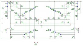
Well here it is latest and most probably final CFB X design.
Supersymmetry is definely possible but I am yet to full investigate the possibilities to see if i like it better than this balanced version.
I might even start a seperate thread.
Tim
Well here it is latest and most probably final CFB X design.
Supersymmetry is definely possible but I am yet to full investigate the possibilities to see if i like it better than this balanced version.
I might even start a seperate thread.
Tim
Attachments
whoops made a mistake
R40 and R36 are surposed to be 15k, but it isn't critical in the above circuit.
and i forgot to mention that i decided to make the circuit single supply.
R40 and R36 are surposed to be 15k, but it isn't critical in the above circuit.
and i forgot to mention that i decided to make the circuit single supply.
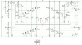
100W Super Symmetrical Current Feedback Aleph X
Sorry i'll try again
This is the same circuit as per the CF Aleph X but with added super symmetry feedback.
super symmetry wasn't as simple to add as i though because the improved common mode rejection, would reject any common mode biasing

But i sorted it out and here it is.....
Sorry i'll try again
This is the same circuit as per the CF Aleph X but with added super symmetry feedback.
super symmetry wasn't as simple to add as i though because the improved common mode rejection, would reject any common mode biasing
But i sorted it out and here it is.....
Attachments

The.Long.and.Winding.Load
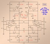
Now I am retiring from this thread, posting my final drawing.
Function: works well
Sound: much better than I expect
Many thanks: to Nelson Pass
And thanks for all of your attention and interest.
🙂 JH 🙂
PS. I am preparing to post this to PASSDIY if this has a quality for it.
Now I am retiring from this thread, posting my final drawing.
Function: works well
Sound: much better than I expect
Many thanks: to Nelson Pass
And thanks for all of your attention and interest.
🙂 JH 🙂
PS. I am preparing to post this to PASSDIY if this has a quality for it.
Attachments
Re: Re: Bridging amplifiers
Nelson, sorry for coming in so late, but would'n you say that the MAX435/436 would be a neat front-end for this?
Jan Didden
Nelson Pass said:
In point of fact there is something new here, and you seem
to have missed the essence of it.
Nelson, sorry for coming in so late, but would'n you say that the MAX435/436 would be a neat front-end for this?
Jan Didden
Alas, manufacturers seem to no longer want to show us
the interior of their chips, even simplified diagrams.
I wonder why that would be?
In any case, it's not possible for me to tell from the data sheets.
the interior of their chips, even simplified diagrams.
I wonder why that would be?
In any case, it's not possible for me to tell from the data sheets.
http://www.maxim-ic.com/appnotes.cfm/appnote_number/692 fig 2. Very rudimentary, of course. Basically it looks like a couple of AD846's sans the buffers. Usefull chip for converting a differential voltage signal into a differential current signal. The Z-terminal is of course what would be the inverting input in a "so-called CFB😉 " opamp.
Jan Didden
Jan Didden
janneman said:Usefull chip for converting a differential voltage signal into a differential current signal. The Z-terminal is of course what would be the inverting input in a "so-called CFB😉 " opamp.
I would have thought so, but notice things like the different
current draw versus the Z resistance.
Return with new-building
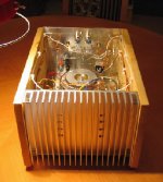
Last week I finished three new Monolithic SuperSymmetries for fun. To these new gears, I gave two changes. One was change of the original EI transformer of 300VA (2x12V secondary) to Toroidal of 400VA. Another was replacement of the current boosting transistor MJ802/4502 with MJ15003/4 (in the next opportunity, I would try with Darlington transistors). Oh.... I also newly arranged one thermistor (6ohms, 7A, of outer dia. of 22mm) in the primary side of the transformer.
I had 1-week listening trial before the final launching of the gears and clearly felt better sound in mid and high frequencies. In addition, I got better dynamics when I tried movie sound tracks. I have no idea whether this improvement happens due to new transistors or new transformer or both of them. It comes one step closer to my own ideal sound (imagination).
In this weekend, I am going to connect one amp for one speaker by paralleling amp’s left and right channels to one mono unit. Of course, I need two amps to do this. It is not a problem because I have three now. This is mainly to increase output current to double capacity.
By the way, in this new-building, I again used hard wiring instead of using PCB. This means inside looks rather ugly. Very much ugly compared to the beautiful inside look of Pass XA-100 which I saw from the picture in Japanese Stereo Sound. Hmmm…. I have to think about using PCB if I build any next project and make the amp case wide, flat and beautiful, for example like Pass XA-100.
😎
Attachments
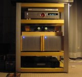
Could not wait
Here are two mono blocks. Well, it seems that the speakers no more hungry for curret. They roar from the deeper end. (Mmmm........... I should have used dalington TRs.)
To me, your ugly stuff still looks pretty. Probably, the effect is from your name behind them. 😉
Here are two mono blocks. Well, it seems that the speakers no more hungry for curret. They roar from the deeper end. (Mmmm........... I should have used dalington TRs.)
To me, your ugly stuff still looks pretty. Probably, the effect is from your name behind them. 😉
Attachments
Thanks, Hugo.
For your info. I introduced minor touch when I did paralleling circuits. The input resistors were originally arranged first 10K and behind it 47K to the ground, but their positions are now changed, i.e. first 47K to the ground and behind it 10K. In addition, I newly introduced the output ¡°ballast¡± resistors (reference: http://www.national.com/an/AN/AN-1192.pdf) of 10W 0.11Ohms (actually, 5W 0.22/parallel/5W 0.22). I have no idea about technical details of the ballast resistors, but I understand that they take role to help separation of the two amp units as independent even if they are paralleled. Anyhow, I found that, with or without the ballast resistors, the paralleled mono blocks show output offset voltages at less than 10mV. I should be happy with these low offsets as I got them with no effort of matching components.
😎
hi ! jh6you
nice stuff . i like it ,sepecially wood side of your amp.
i want to know how you got the wood side in shanghai.
you processed it yourself or make somebody do it?
nice stuff . i like it ,sepecially wood side of your amp.
i want to know how you got the wood side in shanghai.
you processed it yourself or make somebody do it?
Hi, John-china
I got the wood from Ikea (Yi Jia) near to Shang Hai Ba Wan Ren Ti Yu Guan. They had many different panel sizes. My choice was the size of 15mm/190mm/1200mm (t/w/l). I cut them myself with Bosch GST 100 BCE jigsaw. The wood was soft for me to handle easy, but was strong enough to be part of the heavy box.
I ordered heat sinks and aluminium plates from Ke Ji Jing Cheng, Bei Jing Dong Lu. I drilled all bolt holes myself with Bosch GRS 14,4-1 cordless screwdriver drill. To keep the holes to the correct positions, I made drawings using PowerPoint, and print them out on the paper, and glued them to the plates. In addition, when I drilled the holes, I gave 1mm margins to the required hole sizes.
All work done on the kitchen table.
Hope this info. will help.
Regards
To whom has interest.
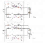
The enclosed sketches show how I tried two alternatives.
Fig.1 demonstrates how I paralleled the amps.
Fig.2 demonstrates how I did bi-amping.
Speaker is Audio Physic Yara (4 ohms 90dB).
For the tight bass sound, I vote for the alternative 1.
For overall sound, I however vote for the alternative 2
😎
Attachments
- Status
- Not open for further replies.
- Home
- Amplifiers
- Pass Labs
- Monolithic SuperSymmetry with Current Feedback