Nelson Pass said:Excessive sibilance in X circuits usually means too much
feedback. I suggest lowering the loop gain, or throwing
some away with resistance to ground at the "-" inputs.
 😕
😕 
What is the primary effect that causes sibilance ?
Distortion ? Peaks in the frequency response ?
If the circuit works as X, it should have very low distortion and independent from X also flat frequency response .
Is it the hall of 1000000 echoes ?

The moment of testing the Pmax and Vppmax of my high power version has come.
New trouble: The amp does not like paralleled loads.
I paralleled 4 33ohm/20W resistors to get a 8ohm/80W.
It does not really oszillate but packages of oszillations occur in one halfwave.
So I decided to my test-speaker and looked for the clipping.
75Vpp 😎 before clipping for a few seconds, the speaker smelled terribly, but survived.
I paralleled 4 33ohm/20W resistors to get a 8ohm/80W.
It does not really oszillate but packages of oszillations occur in one halfwave.
So I decided to
my test-speaker and looked for the clipping.75Vpp 😎 before clipping for a few seconds, the speaker smelled terribly, but survived.
It looks like the problems (partly) come from unproper grounding 🙄
No star grounding...
With little grounding mod it also works with the resistor(s)-load.
88W with 24V rails not too bad and 225W with 36V rails ( but who needs that ) is possible with paralleled output Fets.
No star grounding...
With little grounding mod it also works with the resistor(s)-load.
88W with 24V rails not too bad and 225W with 36V rails ( but who needs that
) is possible with paralleled output Fets.With the resistor load the amp gives 68Vpp = 72W.
There was 75Vpp into the speaker, may be because the coil got so and the resistance/impedance increased and thus the Vpp.
There was 75Vpp into the speaker, may be because the coil got so
and the resistance/impedance increased and thus the Vpp.Nelson Pass said:Excessive sibilance in X circuits usually means too much
feedback. I suggest lowering the loop gain, or throwing
some away with resistance to ground at the "-" inputs.
Thanks, Nelson Pass. I will try one of them or both.
By the way, the sibilance is not very excessive. It is not excessively riding on top of the integral part of the music. Probably, it might be a side effect of the high sensitivity speakers (97dB) I am using. Today I reduced the gain of BOSOZ from 3 (9.5dB) down to 1.5 (3.5dB). I feel as if the "ss"sound got relaxed to "s."
JH
PS. I am a real fan of the X-circuit. 🙂
Nelson Pass said:throwing
some away with resistance to ground at the "-" inputs.
Hey, that looks little bit like my circuit from March 16, 😉
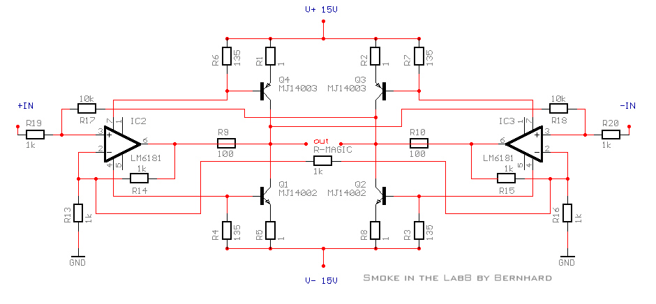
Actually in this circuit the "-" inputs are the ones labeled "+" on the op amps.
The excessive sibilance and other effects appear to simply be too much feedback, which for X circuits results in a "hall of mirrors" effect, not so different from the instabilities seen in ordinary feedback amplifiers.
For this reason X circuits are best implemented as simple gain stages with minimal open loop gain. The advantages offered by the SuperSymmetric topology are high objective and subjective performance with simple circuits, so of course there is no conflict.
Close but no cigar
take a look at figure 53 in the AN815 datasheet from Analog Devices. The test explaining it says it will create a differential amplifier circuit that has absolute symmetry - Really close, it even has a X clearly made in the circuit, with the two inverting inputs tied to each other... Interesting reading. So close, so far.
As for working on the amplifer, well life has a way of intruding on our plans - thus I have not been able to spend time with an iron - only thought experiments while on the train back and forth from work. I last left you with the thought of expanding the circuits of the opamps for clues.
Sooo. Hugo or Bernard, if I can so impose on you and your sim skills - I want to do it, I just don't have the time at the moment. Here is the present thought experiment. How about building two long tailed pairs, with a basic current source to bias it. Tie input 2 of each pair together, with Magic Resistor. Take the two outputs of each pair to serve as the inputs to our 549's or 541's. Inputs to the entire circuit would be + or - from our source, connected to a line drawn back from the output pin of the power opamp on the otherside of the load. These two connected together would then become the input for input #1 on the longtailed pair (perhaps with some sort of buffer).
Choice of active devices should be based on 1) accuracy, 2), simplicity of circuit (such as using one of the common substrate transisors containing a differential setup) and 3) availabilty. All we need it to do is accurately create our signal - so heresy of heresy, plain old tansistors maybe? This part of the circuit does not need to provide gain, we have plenty in the 549s. No great concern of its output impedence since it will connected to the input of the 549 which have very high input impendence. I think you get the drift.
Depending on how this is implemented, it will have a small part count taking up little space, and can be built very inexpensively. I also think that it could be used to drive several pairs of the PowerOpAmps, thus allowing for a highpower version that ChipAmp folks could build.
Thoughts? Nelson, did I get this right or have I screwed up my thinking?
Re: Close but no cigar
What is a long tailed pair ?
Could you draw a kind of simplified schematic ???
Sawzall said:How about building two long tailed pairs, thinking?
What is a long tailed pair ?
Could you draw a kind of simplified schematic ???
Nelson Pass said:
The excessive sibilance and other effects appear to simply be too much feedback ...
Attached is another experiment for the tuning of the sound. Introducing new R1/ R3 of 20k and R15/R16 of 10k, I have tried variation R0 with 220, 500 and 1k. The loop gain changes lower when R0 goes bigger. The signal gain also changes--e.g. about 13.3dB with 220, 12.6dB with 500 and 11.4dB with 1k.
My Final choice is R0 of 500 (subjective choice).
JH
Played CDs:
- Homage to Sarasate, Rachel Barton violin, Samuel Sanders piano (Dorian DOR-90183)
- Mahler Symphonie No.4, Leonard Bernstein, Concertgebouworkest Amsterdam (Deursche Grammophon 423 607-2)
- Cassandra Wilson Blue Light 'til Dawn (Blue Note CDP 0777 7 81357 2 2)
Attachments

First time for everything
Bernhard, I am gonna try to attach the image of the longtail concept. I need to get a simple program to draw schematics.
This is pretty much straight from the book - the long tail (differential amplifer) design has been done from the most simple to the most extreme. So it is very likely that a good design can be lifted from the frontend of another amplifer -- thats if this works, which I think it will.
Attachments
Given up on the AD811...
Progress report.
Well, after a full weekend of playing with the AD811 I have given up. It just seems impossible to get this chip to work properly, it constantly breaks into oscillation.
I have tried many variations on the IC opamp schema, cut a little pcb for the chip with the recommended layout, cooked 3 of the 4 chips I had, and in desperation I even tried just building a simple amp stage using one 811 and the app notes, and that was just as bad!
Arghhhh!!!!
Next step- get some LMs and give them a go😉
Re: Given up on the AD811...
Could you post your schematic ?
You know I had oszillation problems like hell too, but I fixed it
May be I can help.
pinkmouse said:Well, after a full weekend of playing with the AD811 I have given up. It just seems impossible to get this chip to work properly, it constantly breaks into oscillation.
Could you post your schematic ?
You know I had oszillation problems like hell too, but I fixed it
May be I can help.
JH,
referring to your post 608/610 I don't know why the input resistor affects the square.
May be I should try that too ? 🙄
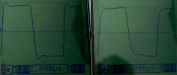
My high power circuit @ 100kHz left uncompensated, right overcompensated.
The overshooting is not 100% symmetric.
No ringing, had that before also... just overshooting.
referring to your post 608/610 I don't know why the input resistor affects the square.
May be I should try that too ? 🙄
My high power circuit @ 100kHz left uncompensated, right overcompensated.
The overshooting is not 100% symmetric.
No ringing, had that before also... just overshooting.
Attachments
Hi Bernhard
National application note OA-25, http://www.national.com/an/OA/OA-25.pdf, reads: "With a CFA amplifier, stabilization is accomplished by adjusting the feed back resistor. Thus one component, the feed back resistor, controls the phase and gain margin of the amplifier." Meanwhile, Nelson Pass has informed us that, when circuits are simpler and loop gains are lower, X-circuits works better.
In my circuit, the increased input resistors lower the loop gain on the "+" input side and the increased R0 lowers the loop gain on the "-" input side so that stability improves. Meanwhile, R15 and R16 values control the frequency bandwidth. I am not 100% sure of my understanding in these ways, but at least the circuit responds so.
JH
PS. I wonder which circuit you are referring to. The overshoot shown in your post seems to be due to the phase shift in high frequencies.
jh6you said:National application note OA-25, http://www.national.com/an/OA/OA-25.pdf, reads: "With a CFA amplifier, stabilization is accomplished by adjusting the feed back resistor. Thus one component, the feed back resistor, controls the phase and gain margin of the amplifier." Meanwhile, Nelson Pass has informed us that, when circuits are simpler and loop gains are lower, X-circuits works better.
In my circuit, the increased input resistors lower the loop gain on the "+" input side and the increased R0 lowers the loop gain on the "-" input side so that stability improves. Meanwhile, R15 and R16 values control the frequency bandwidth. I am not 100% sure of my understanding in these ways, but at least the circuit responds so.
PS. I wonder which circuit you are referring to. The overshoot shown in your post seems to be due to the phase shift in high frequencies.
JH,
my squarewaves belong to my high power circuit.
I read the application notes too...
Maybe in my circuit it is also a little different because of some more external parts.
As you know, with my standard circuit I did not have any oszilation problems.
I'm at work and can not go into detail today evening I try to understand what happens in your circuit.
Bernhard said:JH,
No ringing, had that before also... just overshooting.
I doubt one can really pick up ringing with the type of instrument you are using.
Bernhard said:
I try to understand what happens in your circuit.
Look forward to hearing soon...
By the way, the paper, http://www.tvhandbook.com/support/pdf_files/audio/Chapter13_4.pdf, reads: "The overshoot of a device is the amount by which the peak of the square wave exceeds steadystate positive or negative amplitude, as shown. Large overshoots are indicative of peaking or excess phase shifts in the high-frequency response of the device under test. The maximum overshoot is normally the parameter specified, but the subjective appearance of the overshoot is also of interest. Well-behaved devices will have smooth overshoot, symmetrical on both positive and negative peaks. Overshoot normally occurs only on the leading edges of a square wave. However, if the device is linear-phase, as are many digital filters, there will be symmetrical overshoot on both leading and trailing edges."
JH
Just have watched out the movie, The Hours ...
grataku said:
I doubt one can really pick up ringing with the type of instrument you are using.
Oh yes it can 🙂
Thats not a graphical multimeter, it calls itself a signal computer...
jh6you said:
Look forward to hearing soon...
By the way, the paper, http://www.tvhandbook.com/support/pdf_files/audio/Chapter13_4.pdf, reads: "The overshoot of a device is the amount by which the peak of the square wave exceeds steadystate positive or negative amplitude, as shown. Large overshoots are indicative of peaking or excess phase shifts in the high-frequency response of the device under test. The maximum overshoot is normally the parameter specified, but the subjective appearance of the overshoot is also of interest. Well-behaved devices will have smooth overshoot, symmetrical on both positive and negative peaks. Overshoot normally occurs only on the leading edges of a square wave. However, if the device is linear-phase, as are many digital filters, there will be symmetrical overshoot on both leading and trailing edges."
JH
Just have watched out the movie, The Hours ...
JH,
I know what is overshoot and I know what is ringing, the manufacturers always show their nice scope photos in their data sheets and application notes 🙂
I see you have 10k feedback, I even tried 47k, no cure of my oszillation problem.
To slow down the amp enough to kill oszillation like this, I guess I would have to use feedback in the megaohm range. No thanks...
A bigger input resistor, 10k instead of 1k what I have, did not help.
The oszillations were gone at low levels, but at high levels they came back.
I did not post yet, what I did to make the oszillations disappear 😉
Bernhard
- Status
- Not open for further replies.
- Home
- Amplifiers
- Pass Labs
- Monolithic SuperSymmetry with Current Feedback