 dang! i'd be happy with just 1 (one)!
 Bernhard said:
any Results ? 🙁
I made a mix of your madness and my mosfet circuit and it seems to work.
Didn't spend much time on it, the weather's too good and the garden too nice.😉
I didn't play with R-values, didn't apply a squarewave, didn't build it, only a sim with 1Khz sinewave.
I'll mail you the circuit.
Good luck.
/Hugo – loves JH’s female approach…😎
Attachments
nevermind
damm.. why didn't someone remind me that headphones use a common ground? Only once I started to put it together did it dawn on me.
damm.. why didn't someone remind me that headphones use a common ground? Only once I started to put it together did it dawn on me.
Got it working with several changes in the circuit.
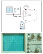
But this is just before clipping.
Unbalanced.
4 Ohm load.
PSU is only 13V DC. Too bad... I have two 18V transformers, each 110V primary, connected in series for 220V.
Now only one is loaded on the secondary, so the other works as current limiter 25V-->13V
Just very glad, the oszillations have gone
But this is just before clipping.
Unbalanced.
4 Ohm load.
PSU is only 13V DC. Too bad... I have two 18V transformers, each 110V primary, connected in series for 220V.
Now only one is loaded on the secondary, so the other works as current limiter 25V-->13V
Just very glad, the oszillations have gone
Attachments
Re: nevermind
Just cut off the jack and put a four pins neutrik connector in its place.
Sawzall said:damm.. why didn't someone remind me that headphones use a common ground? Only once I started to put it together did it dawn on me.
Just cut off the jack and put a four pins neutrik connector in its place.
Bernhard said:
Just very glad, the oszillations have gone
How did you get rid of the oscillations? Or where the changes to numerous to point out the exact reason?
/Hugo
Netlist said:
How did you get rid of the oscillations? Or where the changes to numerous to point out the exact reason?
/Hugo
Still oszillating like hell The progress was with feedback from OP output instead Amp output, but this is not correct.
I tried everything, 100p from pin 3 to gnd, from pin 2 to pin 6, across feedback R to other side, from pin 3 left to pin 3 right, just everything.
Output Power
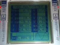
Being interested in the output power of the amp, I measured peak AC voltage across the emitter resistor of 0.22R, as sown in the attached figure. The peak AC voltage appears about 0.5V before passing the clipping point. It means that peak AC current is of 0.5/0.22 = 2.27A. Since the applied load is 8 ohm load, the maximum output power for the 8 ohm load is estimated as (2.27x2.27/2)x8= 20W.
Just for your info, and for your comment if any.
JH
- At vertical scope scale of 20mV/div
- 10x probe
Attachments
Bernhard, did you connect a load? If yes and it is 8ohm, try with something like 100 ohm.
If you have a variac, try slowly rising the supply, and look what happens. Why are your BC550/60 collectors connected to your OP's supplys? Are you not just making a current source to the OP's like that? Should you not connect the bases to the OP's + & -?
Just some thoughts, mainly because I don't understand the BC connection.
JH, if your Fluke is a true RMS DMM, you can measure the voltage and the current directly over/true the load, multiply them and you also have the RMS-power. Looks like you have some nice clean 18W over there
/Hugo😉
Netlist said:Bernhard, did you connect a load? If yes and it is 8ohm, try with something like 100 ohm.
If you have a variac, try slowly rising the supply, and look what happens. Why are your BC550/60 collectors connected to your OP's supplys? Are you not just making a current source to the OP's like that? Should you not connect the bases to the OP's + & -?
Just some thoughts, mainly because I don't understand the BC connection.
/Hugo😉
Netlist,
with or without load, the same thing.
Load is a 4 ohm speaker.
The BC550/60 form simple constant voltage sources which step down the the 24V to 15V, on the collectors is always +15/-15V regardless of the current flowing.
The current of the OP flows trough the bias resistor and the BCXXX.
The joke is that in the abracadabrasimsalabim everything is perfect.
The sine is clean to 72Vpp across a 8ohm load.
According to the application where i got my inspiration this step down works to 36V rails.
But I believe it will work to 300V rails with the right transistors.
Now I got maybe success by placing a few caps somewhere, but I am not shure...
I think I am the lucky guy with my bad current limiting PSU, because otherwise I would have sent all the expensive mosfets to hell already

JH,
I was kidding about the Vpp thing... 😉
...because it looked like you wanted to explore how close the voltage swing can come to the rails.
Also Vpp is worthless in power calculation imho.
In my circuit with mosfets 6V below rails everything is ok, above starts clipping.
24V-6V=18V
x4=72V
72Vpp/sqr2=50,9Vrms
36Vop/sqr2=25,5Vrms
/8ohm=3,2A
*25,5V=80W
Right ? 😕
I came late into this topic, just noticed it a day, or 2 ago, but after glimpsing through, the basic design concept leaves me with a feeling that a very low power design could be used as an affective DAC IV stage for DAC's with balanced current outputs.
Any thoughts?
Any thoughts?
Bernhard said:
Right ?
According to the definition, the power is the rate at which electric energy is transferred to any device (the load) through which the charges flow. Therefore, if maximum Vrms of 25.5 is maintained across the load and maximum Irms of 3.2A continuously passes through it, and in addition, if there is no phase shift between Vrms and Irms, your maximum output power of 80W to the load should be correct. 😎
JH
It seems like the speaker cable acts like an antenna.
One speaker is ok, two in parallel gives oszillations.
But it works so far.
Some little glitches when close to clipping.
There are five ( three... ) new caps, the one in the middle helps a lot, the upper make the oszillations disappear and the lower make them come back.
How can that be ?
This is my latest circuit:
An externally hosted image should be here but it was not working when we last tested it.
I am glad to see that your circuit is well developing to a giant.
When I need high power, I might choose yours. 😉
All the best
JH
When I need high power, I might choose yours. 😉
All the best
JH
Think it will work/help?
After a search of CFB opamps, the LT1207 seems very promising. Its a dual, so that cuts down on the number of tiny connection. Runs from a varity of voltages, and has 250mA of output at minimum - and just as signficant for this project, it can sink most of that load too.
But the part that I think makes it worth investigating is that it has a pin for connecting an external compensation network. This looks interesting for a couple of reasons - one it might increase the stability of the resultant amp, two, in simulations with the 811, it looks like there is a slight tilt upward in the response curve - the compensation network is supposed to get rid of this. The "downside" of this network is that it reduces the bandwidth, down to say 35MHz. That might not be a bad thing.
It also has a current set pin that allows you to play with the quiescent current. Couple of possibilites here too. One, it allows you to shut down the amp in 1uS by opening or connecting to +V. Two, you can play with slew rate independent of feedback resistor setting.
The dual package offers the ability to reduce capacitance on the inverting to inverting connection to almost nothing - something that needs to be minimized. Can afford better bypassing caps since you need 1/2 as many.
12.88 each from Digikey. I ordered a couple - will let you know.
Re: Think it will work/help?
Go on! Build it. If you don't get oscillations, you'll have a very fast Headphone amp.
/Hugo - Good luck 😉
Sawzall said:After a search of CFB opamps, the LT1207 seems very promising.
Go on! Build it. If you don't get oscillations, you'll have a very fast Headphone amp.
/Hugo - Good luck 😉
- Status
- Not open for further replies.
- Home
- Amplifiers
- Pass Labs
- Monolithic SuperSymmetry with Current Feedback