Bernhard said:Nobody interested in the high power version ? 😕
I can cook eggs on my heatsink 🙁 3MHz now
Sure we all are.
(At least I am)
1.8 -3Mhz? Scope pictures? Time to dig up some caps! 😉
Pictures, drawings, findings, sound impression... Zip everything together and post...post all night long...🙂

No, seriously, did you connect speakers and listen?
/Hugo - still building, and even listening to a mono AlephX HighPower amp.😎
Thanks, I 'll look into it although my probes are brand new and the input square from the sign. generator looks great.
Hey Bernhard, you mean to say your amp oscillates? I renew Netlist request!
Hey Bernhard, you mean to say your amp oscillates? I renew Netlist request!
Netlist said:
1.8 -3Mhz? Scope pictures? Time to dig up some caps! 😉
Pictures, drawings, findings, sound impression... Zip everything together and post...post all night long...🙂
No, seriously, did you connect speakers and listen?
This LM6181 is a beast


It does not make any sense if I post the picture from the scope.
I think everybody nows how a sine looks. 😉
My scope has a multimeter that shows everything: Frequency is 3,05MHz with modifications, V0p is full swing to the rails 😡
With 100nF across the 10k feedbacks, the mosfets get melting hot in seconds.

Also I have loud 100Hz noise.
Now I have tried the NE5534 instead.
Everything perfect:
No noise.
No offset ( 0,0065 V ). Best result ever.
No oszillation.
No heat. 130mA through each Mosfet.
No supersymmetry
I have no idea what to do about the LM.
May be the gain is too high.

SOS, please
Re-adjusted the 10X probe for the proper compensation.
And measured at 20kHz on vertical scale of 1V/div.
Arrrrrrrrrrrr.................
Funny.................
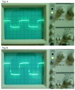
When output sine wave is at 25V (peak to peak), the sq wave is as shown in Fig. A. But, when the output sine wave passes beyond 25V (ptp), the sq wave changes as shown in Fig.B. I can't understand this. What's wrong...? Sigh.
JH
PS. But, the sound is still like a sweet green apple.
Re-adjusted the 10X probe for the proper compensation.
And measured at 20kHz on vertical scale of 1V/div.
Arrrrrrrrrrrr.................
Funny.................
When output sine wave is at 25V (peak to peak), the sq wave is as shown in Fig. A. But, when the output sine wave passes beyond 25V (ptp), the sq wave changes as shown in Fig.B. I can't understand this. What's wrong...? Sigh.
JH
PS. But, the sound is still like a sweet green apple.
Attachments
Bernhard, which schematic are you using now?
Is it some of the ones you posted before?
Maybe it's designed with the NE's in mind and it's unlikely that you can just swap them with LM's without redesigning some or more things.
JH,
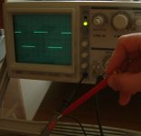
The squarewave in fig. B is due to the female touch on your probes.
No, to me it looks like a perfect normal clipped squarewave.
Perhaps 25Vpp is the limit for your amp. But squarewave experts will be capable of giving you a better technical explanation.
/Hugo
Is it some of the ones you posted before?
Maybe it's designed with the NE's in mind and it's unlikely that you can just swap them with LM's without redesigning some or more things.
JH,
The squarewave in fig. B is due to the female touch on your probes.
No, to me it looks like a perfect normal clipped squarewave.
Perhaps 25Vpp is the limit for your amp. But squarewave experts will be capable of giving you a better technical explanation.
/Hugo
Netlist,
it is the schematic that I have sent you by email. (Also posted here, uses 2SJ/2SK Mosfets)
Its made for the LM but it fails in reality.
But with the NE for which it was not made, it works.
The waiter from the coffee shop round the corner told me, it could be a ground loop that causes oszillation, but the LM is just too fast.
May be the idle current is too high also.
I have tested the circuit with NE and 27V rails, no problem.
it is the schematic that I have sent you by email. (Also posted here, uses 2SJ/2SK Mosfets)
Its made for the LM but it fails in reality.
But with the NE for which it was not made, it works.
The waiter from the coffee shop round the corner told me, it could be a ground loop that causes oszillation, but the LM is just too fast.
May be the idle current is too high also.
I have tested the circuit with NE and 27V
rails, no problem.keep trying
I am keeping at it. Trying different CFB's in the AD family, with lower slew rates, faster settleing times. etc. Basically AD's catalog of CFB's.
The issue is mounting these SOIC's. Am ordering some of the little protoboards for Digikey.
Don't quit guys - we will get higher power or bust!
I am keeping at it. Trying different CFB's in the AD family, with lower slew rates, faster settleing times. etc. Basically AD's catalog of CFB's.
The issue is mounting these SOIC's. Am ordering some of the little protoboards for Digikey.
Don't quit guys - we will get higher power or bust!
Re: keep trying
The LM got 2kV slew rate. No wonder...
Did You try my high power circuit ? Same problems with LM ?
Sawzall said:I am keeping at it. Trying different CFB's in the AD family, with lower slew rates, faster settleing times. etc. Basically AD's catalog of CFB's.
The issue is mounting these SOIC's. Am ordering some of the little protoboards for Digikey.
Don't quit guys - we will get higher power or bust!
The LM got 2kV slew rate. No wonder...
Did You try my high power circuit ? Same problems with LM ?
Re: SOS, please
JH,
The top graph seems normal now, no sign of probe maladjustments.
As for the lower graph, it is not uncommon for amplifiers with not enough stability margin to break into oscillations or oscillatory bursts, like here, with increased output level. Practically all capacitances and other specs of semiconductors are voltage- and current level dependent. In a certain sense, your (and anybody else's) amp changes its character with output level.
The only sure way I know to cure this is to improve the stability margin until you can go up to max output with a clean square wave. And oh, dont forget to test with some cap loading at the end of the speaker cable (like 1uF // 8Ohms). The square wave can have longer rise/fall times with cap loading, but should not lose its integrity.
Ahh, such are the pleasures of amp design....
Jan Didden
jh6you said:Re-adjusted the 10X probe for the proper compensation.
And measured at 20kHz on vertical scale of 1V/div.
Arrrrrrrrrrrr.................
Funny.................
When output sine wave is at 25V (peak to peak), the sq wave is as shown in Fig. A. But, when the output sine wave passes beyond 25V (ptp), the sq wave changes as shown in Fig.B. I can't understand this. What's wrong...? Sigh.
JH
PS. But, the sound is still like a sweet green apple.
JH,
The top graph seems normal now, no sign of probe maladjustments.
As for the lower graph, it is not uncommon for amplifiers with not enough stability margin to break into oscillations or oscillatory bursts, like here, with increased output level. Practically all capacitances and other specs of semiconductors are voltage- and current level dependent. In a certain sense, your (and anybody else's) amp changes its character with output level.
The only sure way I know to cure this is to improve the stability margin until you can go up to max output with a clean square wave. And oh, dont forget to test with some cap loading at the end of the speaker cable (like 1uF // 8Ohms). The square wave can have longer rise/fall times with cap loading, but should not lose its integrity.
Ahh, such are the pleasures of amp design....
Jan Didden
Bernhard
In trying to get my Xklone to work I have been reading lots of Datasheets and Ap. notes on op-amps, and all of the fast ones seem to need some sort of special routing/earthing and pin shielding. It may be worth making up a PCB with these recomendations and giving it another go, P2P may just be not up to the job with these new op-amps.
In trying to get my Xklone to work I have been reading lots of Datasheets and Ap. notes on op-amps, and all of the fast ones seem to need some sort of special routing/earthing and pin shielding. It may be worth making up a PCB with these recomendations and giving it another go, P2P may just be not up to the job with these new op-amps.
Re: Re: SOS, please
Thanks for the comment, Jan Didden.
Accordingly, I re-thought about the principle of feedback and stability.
Trying reduction of loop gain, I switched the input resistor value from 10k to 15k, with a positive result. The clean square wave maintained untill the voltage swing reaches to 35Vpp. I'm going to increase the resistor value further up to 20k, and will see another result (for further improved stability margin).
Sure of the pleasures... 🙂
JH
PS. Somewhat lower gain is acceptable as the superb BOSOZ drives it.
janneman said:
not enough stability margin
Thanks for the comment, Jan Didden.
Accordingly, I re-thought about the principle of feedback and stability.
Trying reduction of loop gain, I switched the input resistor value from 10k to 15k, with a positive result. The clean square wave maintained untill the voltage swing reaches to 35Vpp. I'm going to increase the resistor value further up to 20k, and will see another result (for further improved stability margin).
Sure of the pleasures... 🙂
JH
PS. Somewhat lower gain is acceptable as the superb BOSOZ drives it.
stability
JH,
This is interesting, because lowering the (closed) loop gain means higher feedback factor which generally makes things worse (as far as stability is concerned).
The fact that in your case it improves with higher input R points to some unwanted (pos) feedback to the input pins. You may want to review your layout (if it's PtP) to make sure there is no unintentional coupling of the output signal to the non-inverting input, and/or no unintentional coupling between the two inputs.
Jan Didden
Yea... again theory and practice... just a joke. 😉
I will look into them, and will come back tomorrow this time.
JH
I will look into them, and will come back tomorrow this time.
JH
Hey guys,
I recommend the
AD8009 1 GHz 5,500 V/µs Low Distortion cfb Op Amp
for:
more accurate and stable oscillation of the amp
&
more ringing and overshooting
I recommend the
AD8009 1 GHz 5,500 V/µs Low Distortion cfb Op Amp
for:
more accurate and stable oscillation of the amp
&
more ringing and overshooting

- Status
- Not open for further replies.
- Home
- Amplifiers
- Pass Labs
- Monolithic SuperSymmetry with Current Feedback