Newbie question
I've read some of the pages on this subject, but not all yet, but i was wondering if it wouldn't be possible to make a preamp using the supersymmetry topology to make a preamp? how about the ad811 in this topology followed by a pga2310 and some kind of output stage?
I've read some of the pages on this subject, but not all yet, but i was wondering if it wouldn't be possible to make a preamp using the supersymmetry topology to make a preamp? how about the ad811 in this topology followed by a pga2310 and some kind of output stage?
Re: Newbie question
Draw us something..😉
/Hugo - Wonders how pinkmouse's circuit is doing?
Kongen said:I've read some of the pages on this subject, but not all yet, but i was wondering if it wouldn't be possible to make a preamp using the supersymmetry topology to make a preamp? how about the ad811 in this topology followed by a pga2310 and some kind of output stage?
Draw us something..😉
/Hugo - Wonders how pinkmouse's circuit is doing?
Re: Re: Newbie question
Badly... Whatever I do to it, Rookie's design seems to be unstable... But I haven't given up yet!😉
Netlist said:/Hugo - Wonders how pinkmouse's circuit is doing?
Badly... Whatever I do to it, Rookie's design seems to be unstable... But I haven't given up yet!😉
Re: Re: Re: Newbie question
That was fast...
Give my circuit a try. The one on post #473.
If you want i can post the one with the resistor values.
On the sim it worked OK.
/Hugo
pinkmouse said:
Badly... Whatever I do to it, Rookie's design seems to be unstable... But I haven't given up yet!😉
That was fast...
Give my circuit a try. The one on post #473.
If you want i can post the one with the resistor values.
On the sim it worked OK.
/Hugo
VFB LM3875 Supersymmetry
I seem to remember that somebody was trying to do SUSY with Lm3875 op amps - any success?
This would cut out the power boosting transistors necessary to ramp up CFB design and the as the chip is already rated sonically would be an interesting combination
I seem to remember that somebody was trying to do SUSY with Lm3875 op amps - any success?
This would cut out the power boosting transistors necessary to ramp up CFB design and the as the chip is already rated sonically would be an interesting combination
Same here PM..
Glad to see it is not just my incomptence causeing the problems. The cap that I suggested worked great in the sim, but added its own problems. Going the other direction with somesort of choke might be something to try...
I probably have the fewest skills of anyone involved in this, but my next step is to actually "blow up" the circuit to look inside the two chips to see if that triggers any good thoughts. Once you "grok", it should come..
I really would like this to work.. conceptually it would mean just add modules to get all the power you need for whatever you wanted, without all noise, distortion etc, or huge parts list.
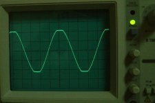
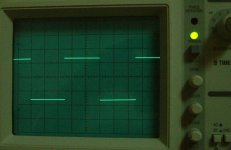
Finally, at 100kHz (1V/Div, probe setting x10).
Here, I see the overshoot and ringing clearly. This however looks OK for me. It must be that two poles (conjugate complex numbers) are in the stable side and so the ringing decaying rather quickly. I imply that the amp is stable. But, since I am not a professional interpreter about the overshoot and ringing, if you tell me any different opinion or any tip, I would much appreciate it. Thanks.
JH
Attachments
Re: Same here PM..
Don't you dare! I am having far too much fun as it is, and it would be nice to see if I come up with something similar to yours!😀
Don't you believe it, I have never built anything from scratch before, my sole experience has been copying others circuits. I feel I am actually learning something, my mac is always online whilst playing around, and I am constantly hopping between this forum, datasheets and other websites to try and work out what is going on, I haven't had so much fun/frustration in ages.😉
Netlist said:
If you want i can post the one with the resistor values.
On the sim it worked OK.
/Hugo
Don't you dare! I am having far too much fun as it is, and it would be nice to see if I come up with something similar to yours!😀
Sawzall said:I probably have the fewest skills of anyone involved in this,
Don't you believe it, I have never built anything from scratch before, my sole experience has been copying others circuits. I feel I am actually learning something, my mac is always online whilst playing around, and I am constantly hopping between this forum, datasheets and other websites to try and work out what is going on, I haven't had so much fun/frustration in ages.😉
New challenge for me:
I need to built a version with +80V DC offset and 300V rails.
So I can direct drive my plasma tweeters and get rid of the transformer.
I need to built a version with +80V DC offset and 300V rails.
So I can direct drive my plasma tweeters and get rid of the transformer.
I have built my high power version, it works so far but there is a clean full power 1,8MHz sine oszillation 🙁
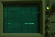
jh6you said:Then, I pressed the square wave button.
The shape is a bit odd, maybe you should take a look at the scope probe adjustment for best sq wave at the input?
Jan Didden
janneman said:
scope probe adjustment for best sq wave at the input?
Example of the input sq wave.
JH
Attachments
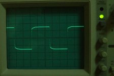
Nelson Pass said:Your output square wave still looks like the probe needs adjustment. I would recheck it.
How do you go about adjusting a probe?
Most of the times there is a little trimmer on the tip area, which allows you to trim the internal cap across the series resistor. (This is with 10x attenuator probes). You connect the probe to a cal signal (which should be available on the scope) and adjust for best-looking square wave.
With straight 1x probes, there still sometimes is a trimmer to adjust for cable cap, but this trimmer may be on the connector of the probe to the scope.
Jan Didden
With straight 1x probes, there still sometimes is a trimmer to adjust for cable cap, but this trimmer may be on the connector of the probe to the scope.
Jan Didden
grataku said:
How do you go about adjusting a probe?
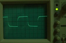
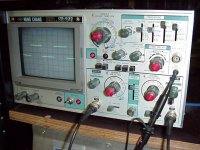
On many scopes you have a calibration output, mine give 0.5Vpp
squarewave. Just hang the probe on that calibration point. On the probe there shoud be a small screw. Turning that calibrates the probe. On the right side of the picture you can see the probe hanging on the calibration point.
/Hugo
- Status
- Not open for further replies.
- Home
- Amplifiers
- Pass Labs
- Monolithic SuperSymmetry with Current Feedback