
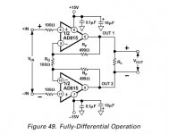
sorta looks like what we are doing here..
as it should since its using two opamps to make a differential amp.
But it does not use the X feedback scheme - thus, its not X.
I have been sitting here at work pondering my existence and the pile of parts I have at home and came up with a strange thought.
Howabout simple headphone amp? the AD811 is a high current and can swing the voltage. The AD8010 can move 200mA - thats enough into a set of high-impedence cans.
Pehaps I can at least be the first that has a MAACFB-X headphone amp.
(tried to throw a quick schematic up here at work, but of course they block transfers..)
Re: sorta looks like what we are doing here..
Why not ?
Rg = R_magic
Now as I wrote, with the LM it was oszillating and heating up after a few minutes. 🙁
After applying Cs which canceled the oszillations, it got incredible hot after seconds.
The guy from the coffee shop round the corner told me that maybe the idle current is much too high and while oszillating, the energy leaves the circuit,
but without oszillation it stays in the circuit and heats it up even more.
Also other things make the idle current suspicious to cause the heat...
Sawzall said:as it should since its using two opamps to make a differential amp.
But it does not use the X feedback scheme - thus, its not X.
Why not ?
Rg = R_magic
Now as I wrote, with the LM it was oszillating and heating up after a few minutes. 🙁
After applying Cs which canceled the oszillations, it got incredible hot after seconds.
The guy from the coffee shop round the corner told me that maybe the idle current is much too high and while oszillating, the energy leaves the circuit,
but without oszillation it stays in the circuit and heats it up even more.
Also other things make the idle current suspicious to cause the heat...
Bernhard
take a look at post #6 in this thread. That is the comparison that should be made here. See, both have the resistor, but the loop from each side of the output is not.
As for the headphones.. using 9v batterys makes the powersupply easy.. Maybe I ought to shut up here. Simple things like this sell for hundreds or thousands of dollars and I could be taking money out of Mr. Pass's pocket. If nothing else, its (and the rest of these manical amp building attempts we have all done) is worth an article in Audio Express. Just promise to change the names so our friends won't laugh at us.😉
take a look at post #6 in this thread. That is the comparison that should be made here. See, both have the resistor, but the loop from each side of the output is not.
As for the headphones.. using 9v batterys makes the powersupply easy.. Maybe I ought to shut up here. Simple things like this sell for hundreds or thousands of dollars and I could be taking money out of Mr. Pass's pocket.
If nothing else, its (and the rest of these manical amp building attempts we have all done) is worth an article in Audio Express. Just promise to change the names so our friends won't laugh at us.😉P2P
Pinkmouse:
>I have been reading Datasheets and Ap. notes on op-amps, and all of the fast ones seem to need some sort of special routing/earthing and pin shielding. It may be worth making up a PCB with these recomendations and giving it another go, P2P may just be not up to the job with these new op-amps.<
Ground planes and careful attention to ground loops is always a good idea. OTOH, I have made >100MHz discrete-device video amps using P2P construction (albeit on top of a multi-layer PCB with separate ground and power planes, and lots of PS bypasses), so I doubt if intelligently implemented P2P will be a performance bottleneck for most opamps.
Think 3-dimensionally, don't be afraid to stack components on each other, use component leads instead of separate wiring, keep everything as densely compact as possible, and use a loupe to insure that your clearances are paper-thin rather than dead-short.
best, jonathan carr
Hi Jonathon, been with us long?😉
Having just built probably the most drastically unstable amp in DIY history, (see earlier posts!), I was just looking at ways to try and minimise component problems so I could hopefully just troubleshoot the circuit in the next version I build.
Having been pooring over notes on these fast amps the designers seem obsessed by correct pcb implementation, with all sorts of dire warnings concerning instability if the boards are routed incorrectly, and I just wanted to pass these warnings along so everyone was aware of them.
I'm sure, as you say, good P2P wiring will work, I just know my last attempt nowhere near reached these conditions!
Anyway, roll on this weekend, when I will attempt a new version, based on Netlist's ideas, and some of my own
Yep
I read all the samethings, PM. Today I ordered some of the SOIC protoboards for Digikey, along with a set of SOIC samples from AD. I bought the first pair of 811 since they didn't sample the part that a human can solder. Looking at the way the little cards are built, for the next try I am going to mount the IC's on the SOIC traces, then solder the signal pins for the 549s within mm's of the 811's. Should be really tight work. Talked to one of the satellite engineering guys in our shop - pointed out that when dealing with higher freq, you just have to pay more attention. Well, we don't have the HF I say. He tells me that any little bit that is either picked up or created in our circuits is going to cause us trouble since we didn't start the design like he would if he was to pick up the iron. Solder close, then clip the ends since they can act like tiny antennas, etc.
Still on the lookout for a slower CF OpAmp. I guess that since they were the solution for highspeed problems before other tricks were developed. I wonder this though. Why do the oscillations grow when they are outside of the bandwidth of the power IC's we are using? I am tempted to take a 549 down to the shop and see what it does when fed a 10mhz signal. Since it is way out of its bandwidth, where does that component go? If it has a high impedence on the inputs on a VFB, so is it reflected back into the 811? like mismatched impedence signals do.. Or is the evil lurking somewhere else.
I think you said it best PM, even if we don't get anything that works, the frustration has been worth it. I know it has rekindled a long silenced passion, and I have learned a great deal. Thanks, NP. (and over in the gainclone world, folks are building amps without ever reading the datasheets. I laugh.)
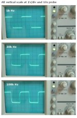
It is very interesting. Yeah, I again increased the input resistor up to 20k. The square wave results are getting even better. They are clean until the output voltage swing reaches 40Vpp. By the way, the output voltage swing starts the symmetrical clipping at 45Vpp.
As regards the feedback loops, please note that I have multi feedback loops both to the non-inverting and inverting inputs. I can't figure out the gain margin, phase margin and stability margin mathematically. However, one thing I see clearly is that the higher input resistor lowers the error current flowing through the inverting input node.
I finally fix the input resistor value at 20k.
JH
PS. The sound of each musical instrument and as a whole is great.
Attachments
jh6,
great job! Actually, this is starting to look so good it's becoming hard to ignore. Plus I have a collection of power trannies that are just dying to get used. Can you keep us up do date with the most current schematic?
great job! Actually, this is starting to look so good it's becoming hard to ignore. Plus I have a collection of power trannies that are just dying to get used. Can you keep us up do date with the most current schematic?
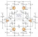
grataku said:
the most current schematic
Here you are.
Attachments
thanks Jh6,
how many pF is the cap in the X feedback?
Have you experimented with higher voltages?
how many pF is the cap in the X feedback?
Have you experimented with higher voltages?
Probably about 5pF, but I do not know the exact value as I made it with a twisted wire of about 50mm long.
No, +/- 15 volts only. I have no plan to try higher voltages in the near future.
JH
No, +/- 15 volts only. I have no plan to try higher voltages in the near future.
JH
It gives quite a distinctive quality of sound--like a "dangerous" mistress.
I'm waiting for the 2nd opinion, 3rd or more...
The sound was better when it had 10k input resistor (higher gain) even though the square waves looked worse. It is however too early to make a conclusion. My BOSOZ is at the gain of 3 for the time being. I will increase the gain of BOSOZ and will see how the sound changes.
JH
Try this I suppose...
Kuei Yang Wang notes in post 16 of the Bridgeclone thread:
Kuei Yang Wang notes in post 16 of the Bridgeclone thread:
Lastly, in the interest of avoiding building FM transmitters instead of amplifiers, please place a very low inductance 1uF or larger capacitor directly across the +V and -V pins of the high speed op-amps (applies to AD811, LM6181/82/71/72 et al).
jh6you said:It gives quite a distinctive quality of sound--like a "dangerous" mistress.
I'm waiting for the 2nd opinion, 3rd or more...
The sound was better when it had 10k input resistor (higher gain) even though the square waves looked worse. It is however too early to make a conclusion. My BOSOZ is at the gain of 3 for the time being. I will increase the gain of BOSOZ and will see how the sound changes.
JH
I seem to recall that when I tried 20 k in the inputs in the AX the squarewave looked worse. Anyways, the squarewave at 100 khz that you showed two weeks ago looked pretty terrific already.
40pp AC with 30vDC supply. Unclipped. The 45 was clipping. Seems damn good to me. What kind of load are you useing JH?
Found an interesting candidate for the headphones - LT1207 Dual 250mA/60MHz. The 250 number is min. Average is 500mA. If I assumed a 32ohm set of cans, thats some stunning numbers. Even into 8ohms it could do 2watts. How to heatsink it is another issue. In the dual it only comes in 16 lead SOIC. Anyone have any ideas about that? Its $15 from Digikey, and LT don't sample it seems, so I need to investigate some more before I take a flyer. `
Found an interesting candidate for the headphones - LT1207 Dual 250mA/60MHz. The 250 number is min. Average is 500mA. If I assumed a 32ohm set of cans, thats some stunning numbers. Even into 8ohms it could do 2watts. How to heatsink it is another issue. In the dual it only comes in 16 lead SOIC. Anyone have any ideas about that? Its $15 from Digikey, and LT don't sample it seems, so I need to investigate some more before I take a flyer. `
It doesn't get any better than that.jh6you said:It gives quite a distinctive quality of sound--like a "dangerous" mistress.
Bernhard said:???????
Sawzall said:40pp AC with 30vDC supply.
I have two girls who have the equal energy of 15, i.e. total 30. I am a lucky man. They never like me or dislike me simultaneously. When one girl likes me, another girl is always opposite. It happens alternately and regularly. Of course I am standing between them, enjoying it.
They always push or pull me alternately. When one girl pushes me away with her energy of 10, another girl pulls me into her with the same energy. I receive total energy of 20 from them and I incline to one side to a point soon I might collapse. But, just before I collapse, they change mind with their opposite direction energy. It repeats...
I swing myself alternating cycles under the peak-to-peak energy swing of 40.
0 to 20,
back to 0,
0 to -20,
back to 0,
0 to 20,
back to 0,
0 to -20,
back to 0,
happy man...
JH
- Status
- Not open for further replies.
- Home
- Amplifiers
- Pass Labs
- Monolithic SuperSymmetry with Current Feedback