re: whassup with MJ802/MJ4502?
allegedly, a pair well designed to be complementary to each other
also available relatively inexpensively, a treat for trialing wild ideas that could blow up devices
mlloyd1
allegedly, a pair well designed to be complementary to each other
also available relatively inexpensively, a treat for trialing wild ideas that could blow up devices
mlloyd1
grataku said:JH,
is there something special with MJ802-4502?...
Bernhard, Those IRFPxxx are the official Pass amp devices.
Definately a good idea!
________________________________________________
Indeed, IR should be very greatful to Nelson, and their slogan should be "The Official Device Supplier To Pass Labs".......
Mark
Definately a good idea!
________________________________________________
Indeed, IR should be very greatful to Nelson, and their slogan should be "The Official Device Supplier To Pass Labs".......
Mark
Re: Re: Re: Re: Maybe .....
Thanks for your comment, Jan Didden.
Your comment is very well aligned with my lesson got in course of the experiment. I will try your recommendation. It seems that once I have tried the 10k, but I do not remember (too many times soldering and resoldering). Anyhow, I will try it again.
By the way, last night I took one CD from my son's room--Metallica, Garage Inc. I played it on, loudly. Wow. The sound was great, lively, no fingernail scraching. The sound did not push me hide at all.
Behind me, my wife said, "What is the problem? Is it related to the sound quality? No? Then, why not just leave it!" Hmmm... No, I will take my effort more to reduce the absolute dc before I give the finish with a pretty dress on...
JH
janneman said:
Please note that the only reference to ground in this circuit comes from through R13 and R14. If one of the output drifts upwards, say the +output for example, there will be current through R2, which will flow through R13 and move up the + input. U1 really cannot do anything about this; it can move the -out terminal up (and will do that) which justs means you get the same situation on the -output and U2. So, in the end, both are sitting happily at the same level, but it has no reference to ground.
Jan Didden
Thanks for your comment, Jan Didden.
Your comment is very well aligned with my lesson got in course of the experiment. I will try your recommendation. It seems that once I have tried the 10k, but I do not remember (too many times soldering and resoldering). Anyhow, I will try it again.
By the way, last night I took one CD from my son's room--Metallica, Garage Inc. I played it on, loudly. Wow. The sound was great, lively, no fingernail scraching. The sound did not push me hide at all.
Behind me, my wife said, "What is the problem? Is it related to the sound quality? No? Then, why not just leave it!" Hmmm... No, I will take my effort more to reduce the absolute dc before I give the finish with a pretty dress on...
JH
MSSCF
Bernhard, do I understand correctly you use the same schematic as JH, but with FET output devices?
JH, if you are interested to investigate this further, I would suggest deleting R13 & R14, replacing R0 with two resistors of 22 Ohms and grounding the midpoint. That should bring the common mode offset back to zero and restore max dynamic range. The input resistance would be 10K, which I think is high enough.
I am really interested in your findings.
Jan Didden
Bernhard said:There must be something wrong, I have below 10mV.
Bernhard, do I understand correctly you use the same schematic as JH, but with FET output devices?
JH, if you are interested to investigate this further, I would suggest deleting R13 & R14, replacing R0 with two resistors of 22 Ohms and grounding the midpoint. That should bring the common mode offset back to zero and restore max dynamic range. The input resistance would be 10K, which I think is high enough.
I am really interested in your findings.
Jan Didden
Re: MSSCF
I am thinking the grounding midpoint, but with a resistor (not to lose the X-effect). Or one R0 with two ground resistors at the both ends of the R0. I will see it tonight.
JH
janneman said:
grounding the midpoint
I am thinking the grounding midpoint, but with a resistor (not to lose the X-effect). Or one R0 with two ground resistors at the both ends of the R0. I will see it tonight.
JH
Re: MSSCF
Bernhard,
Yes, same question, can you show an schematic of your actual circuit?
You have shown a number of designs but don't know which one you are using.

janneman said:
Bernhard, do I understand correctly you use the same schematic as JH, but with FET output devices?
Bernhard,
Yes, same question, can you show an schematic of your actual circuit?
You have shown a number of designs but don't know which one you are using.
janneman said:
Bernhard, do I understand correctly you use the same schematic as JH, but with FET output devices?
Jan Didden
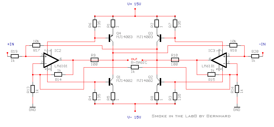
No, this is my circuit:
Playing around with the values gives more ore less gain.
In the end, when the design is final, maybe all N-fets
 , I will determine the values, so that a sinus from CD will drive the amp close to clipping.
Before that, I still got to try so many variations
 ...
...
This is JH's circuit:
http://www.diyaudio.com/forums/attachment.php?s=&postid=148192
This is Netlist's Mosfet circuit:
http://www.diyaudio.com/forums/attachment.php?s=&postid=146241
JH's problem could be, that the -inputs and/or outputs of the OPs are nowhere referenced to ground.
In Netlist's circuit via R9 R10 R15, in my circuit via R9 R13 R14.
Bernhard said:
JH's problem could be, that the -inputs and/or outputs of the OPs are nowhere referenced to ground.
Ok, I looked over every schematic that has been posted here, exept the "Madness" ones. (Just too mad for me) 😉
There is absolutely no way to get rid of the DC without adding R15/16 or adding another R0 and ground the midpoint! (To me)
I tried it with the transistor version on the sim and in real life with the mosfets.
Bernhard, are you sure your last posted schematic is correct?
Without R15/16 I get -14Vdc at the outputs. 😱
That's also the conclusion of JH, but his problem is too much current running when adding them and other R's. (R9-R12)
Isn't the SuperSymmetry gone if you add a ground
between two R0's?
/Hugo
Bernhard said:
[snip]
JH's problem could be, that the -inputs and/or outputs of the OPs are nowhere referenced to ground.
In Netlist's circuit via R9 R10 R15, in my circuit via R9 R13 R14.
Yes, that was also my assessment. It falls into place now. R13, 14 in your circuit are crucial to get the final balance, also common mode. In fact, my suggestion to delete JH's R13, 14 brings the input circuitry to your configuration.
I assume that your "R-magic" determines the closed loop gain?
Jan Didden
I easily could be wrong
but I thought in this amp was supposed to "float" with respect to ground? And with this assumption, DC offset was not material.
(This is as much a question as it is a statement....)
but I thought in this amp was supposed to "float" with respect to ground? And with this assumption, DC offset was not material.
(This is as much a question as it is a statement....)
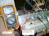
Ok, I have looked again at my DC offset values. 🙂
Worst case is output to ground 0,04 V on side, 0,02 V other side, and 0,02 V between outputs, when the amp is cold.
After warming up worst case is output to ground 0,025 V on side, 0,015 V other side, and 0,01 V 😎 between outputs.
May be these values can be improved further, my resistors are full carbon non magnetic 5% and 10% types
The schematic in post 292 / 03-16-2003 08:50 AM is the real life circuit.
I have tried bypass the magical 1k with 220ohm, does not affect the DC offset, also bias adjustments doesn't.

Msscf
JH,
Well done! Hadn't thought about that one.
Nevertheless, I still think the other solution with the resistors from the neg opamp input to gnd is better. Your common-mode offset indicates that the control is just so-so. It is too much dependent on the resistor values and another amp may be better or worse.
But, if it sounds OK to you, I don't want to argue.
Jan Didden
jh6you said:This one works as I wanted !!!
JH
Congratulations ! 😀
But strange...
...in my circuit, (which, by the way, today is ten days old
 ) I have 1k feedback resistors, which is even lower than your former 1,5k which gave you offset problems.
 Why don't you try some connection to ground ? 😕
 May be you want to go your own way 😉
Bernhard said:
Thanks, Bernhard.
I TRIED IT (INCL. MANY DIFFERENT WAYS).
You would see full of scars on the p2p wires.
JH
Re: Msscf
JH, 🙂
0,13V is still 10x of what I have... 🙄
As I mentioned a few times already, I am free to play around with all values in my circuit even to extremes, and it does not affect DC offset.
So I am also little bit afraid that your circuit is on the razors edge.
JH, 🙂
jh6you said:FIXED !!!
JH
0,13V is still 10x of what I have... 🙄
janneman said:JH,
Well done! Hadn't thought about that one.
Nevertheless, I still think the other solution with the resistors from the neg opamp input to gnd is better. Your common-mode offset indicates that the control is just so-so. It is too much dependent on the resistor values and another amp may be better or worse.
But, if it sounds OK to you, I don't want to argue.
Jan Didden
As I mentioned a few times already, I am free to play around with all values in my circuit even to extremes, and it does not affect DC offset.
So I am also little bit afraid that your circuit is on the razors edge.
jh6you said:
Thanks, Bernhard.
I TRIED IT (INCL. MANY DIFFERENT WAYS).
You will see full of scars on the p2p wires.
JH
And it did not give you lower DC offset ???
Bernhard said:
And it did not give you lower DC offset ???
Incresed to -10V.
Then, suddenly, I got a method how to reduce it !!!
JH
PS. Let us think about positive way.
If we have three different working circuits in this thread, is it bad?
- Status
- Not open for further replies.
- Home
- Amplifiers
- Pass Labs
- Monolithic SuperSymmetry with Current Feedback