I just cranked up the voltage to +/-20V.
There is more idle current running true the amp, 560mA vs. 420mA
20v/18V.
There is a bit more power now compared with 18V.
But I have the impression the sound is getting better.
There's more 'air' around the music. The sound seems more 'detached' from the speakers. A feeling I didn't have till now with this amp.
I keep comparing it with the ZenV4, and although this one is more powerful, the Zen is still preferred (to me) in warmth, detail and the ease of reproducing music.
I would appreciate your comments on this.
/Hugo
Swallow this 

I did not try it. My calculation was 0,65V across emitter resistor + 0,65V base-emitter voltage + 2 x 3,6V for blue LED = 9V.
= 9V.
24V rail voltage - 9V = 15V for the girly-man-chip.
I did not try it. My calculation was 0,65V across emitter resistor + 0,65V base-emitter voltage + 2 x 3,6V for blue LED
= 9V.24V rail voltage - 9V = 15V for the girly-man-chip.
Well..
after slogging thru about 3000 entries on the X threads, a few crispy IC's, I now know how little I knew when I started. And that I still need to learn alot.
541's work, but I think that I will try paralleling two next. You simply need more current than you think you will at first blush. Will try using 0.1ohm/1%/5W on each chips output, but before the feedback is taken from the pair.
I think that the current needs ought to be the first warning to everyone who approachs this design, no matter how you choose to implement the design. It is backwards from what most newbies (including me - wish I could go edit out my posts of stupidity, but oh well) will think until they grasp that the X is different (see endless posts on bias needs). I now have a really good barely used 24v 400va VM transfo that I guess I should turn into a plain old gainclone. Will be ordering a 12v from them with larger gauge windings. It simply is easier to go for a 15Vp supply so that everything can be ran from one really good filter bank.
I have read on the gainclone threads where folks are ignoring the current limiting setting on the chips - don't do it here. Pretty easy to make toast.
Mr. Pass reported that the X's are pretty immune to RF. Be real cool if the chip amp is that way - I have an buddy who would love that - won't cure his RF in phono problem, but would help.
And Benard, I too have had some strange dreams. One of which is just how far can you take the X concept? From source to pre to crossover to amps to drivers? Can you make the differential feedback that long?
after slogging thru about 3000 entries on the X threads, a few crispy IC's, I now know how little I knew when I started. And that I still need to learn alot.
541's work, but I think that I will try paralleling two next. You simply need more current than you think you will at first blush. Will try using 0.1ohm/1%/5W on each chips output, but before the feedback is taken from the pair.
I think that the current needs ought to be the first warning to everyone who approachs this design, no matter how you choose to implement the design. It is backwards from what most newbies (including me - wish I could go edit out my posts of stupidity, but oh well) will think until they grasp that the X is different (see endless posts on bias needs). I now have a really good barely used 24v 400va VM transfo that I guess I should turn into a plain old gainclone. Will be ordering a 12v from them with larger gauge windings. It simply is easier to go for a 15Vp supply so that everything can be ran from one really good filter bank.
I have read on the gainclone threads where folks are ignoring the current limiting setting on the chips - don't do it here. Pretty easy to make toast.
Mr. Pass reported that the X's are pretty immune to RF. Be real cool if the chip amp is that way - I have an buddy who would love that - won't cure his RF in phono problem, but would help.
And Benard, I too have had some strange dreams. One of which is just how far can you take the X concept? From source to pre to crossover to amps to drivers?
Can you make the differential feedback that long?Re: Well..
I have said that the Mosfet circuits that I have used in Alephs and X product have proven immune to RF. No guarantees with reference to integrated circuits.Sawzall said:Mr. Pass reported that the X's are pretty immune to RF.
Oh I understand the chip issue.
That is why it would be so cool if it turned out the chip amp did the same - I think the world is full of otherwise good amps that have RF problems.
(as an aside to others, there are places like Mt. Wilson that would probably keep a florecent bulb lit once started. The FCC and OHSA checked them for enviromental RF last year and few places in the antenna farm were legal... it is gonna be expensive to fix. As you can imagine shielding there is important.)
Antenna Farm
It was time to test the sound.
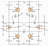
The +/- 15V power supply was connected to the left channel. The dc current through 1 ohm emitter resistor was measured 160mA. Okay. The left speaker was connected to the output terminal. The unbalanced music signal was injected to the input. Yeah, there was music.
The +/- 15V power supply was disconnected from the left channel and connected to the right channel. There was 160mA and there was music too. Yeah...
Finally, to the both channels, the +/- 15V power supplies were connected. The dc current through the emitter resistor of the left channel was measured. Heck...!?!? 1.3A...!?!? Why not 160mA... The right channel was measured. Again, Heck...!?!? 1.3A...!?!? I did not touch any circuit component. When each chennel was tested, the dc current were 160mA. Strange! strange. strange...
Arrrrrrrr... I am getting mad. Blood pressure is reaching high. Would you please save me? What is wrong?
JH
PS. I tried R9-12. They did not solve the above question.
First, what do you mean with channel?
Did you actually build to mono amps?
If so, whats the connection or link between both amps?
Sketch?
/Hugo
Did you actually build to mono amps?
If so, whats the connection or link between both amps?
Sketch?
/Hugo
Netlist said:Whats the connection or link between both amps?
Check grounds!!??
/Hugo
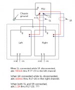
Even though I don't think what I'm about to say will solve your problem I would connect each of the amplifiers (separate cables) directly to the PSU ground avoiding the chassis route. But leave the PSU ground connection to Chassis.
Also is a common practice that the ground connection to chassis be through a low value power resistor to avoid ground loops.
Hope you can solve this strange situation and congratulations for your work I realy admire it

Also is a common practice that the ground connection to chassis be through a low value power resistor to avoid ground loops.
Hope you can solve this strange situation and congratulations for your work I realy admire it
jh6you said:No solution yet. 🙄
JH
Try to connect the grounds as explained by apassgear and drawn here.
Make the ground wires about the same length and as short as possible.
Does disconnecting the source make a difference? Is it balanced or SE?
In your sketch I cannot see the relation between the "chassis ground" and the rest of the circuit, except you connected a point somewhere 'in space' to the ground of your circuit.
Are the "g" points of your amps connected to chassis or only to the grounded components (R13/14) and your additional 100Ohm from output to ground?
(Hope I'm a little clear here) 😱
Measure with an ohmmeter every ground that should be ground;
especially the relation of grounds between both amps and chassis. Should all be close to 0.
Personally, I think you should avoid to use the whole chassis as a ground for now, but that could imply rebuilding a few things

Sorry to disagree a bit on this with you, apassgear, the idea is: the less ground, the less ground loops. Only a few good ground connections should work here. BTW, my amp has no chassis, and as a result also no ground to chassis. 🙂
Anyone correct me if I’m wrong here.
/Hugo – Is certain JH will solve it! With the help of good sleep and some coffee. 😉
Attachments

Netlist,
Any new experiences concerning sound, bipolar vs. mosfet ?
My plan now is to use 25V stabilized --> 20V rails, and 2 x 400W transformers for 2 x 4 channels.
In my Sony 4-channel amps I have 40V rails, so output power should be the same.
With mosfets supply must be about 15V for the OPs.
Any new experiences concerning sound, bipolar vs. mosfet ?
My plan now is to use 25V stabilized --> 20V rails, and 2 x 400W transformers for 2 x 4 channels.
In my Sony 4-channel amps I have 40V rails, so output power should be the same.
With mosfets supply must be about 15V for the OPs.
Bernhard said:Netlist,
Any new experiences converning sound bipolar vs. mosfet ?
/
Hard to compare, since the bipolar version is no more, but with +/-20V and the mosfets, buffered with 2 x 68.000µF the sound is nicely detailed and very punchy. Very deep bass, clean, but a bit aggressive top high, the mid could be better. Still not enough 'air' in the music. But definitely better than +/-15V I guess because of the higher bias.
/Hugo - now listening to Lyle Lovett/Joshua Judges Ruth; a marvellous recording 😉
Netlist said:
Hard to compare, since the bipolar version is no more, but with +/-20V
Exactly +/-20V ? What is your resulting OP supply voltage now ?
Bernhard said:
Exactly +/-20V ? What is your resulting OP supply voltage now ?
2 x 15.5V. As the max voltage of the OP supply is +/-18V this looks safe. The amp is playing for several days now, without a problem.
Read post #380/381 as well.
BTW, the RMS output power per channel is 20W in 4ohm at 400Hz. Measured with true RMS DMM Vrms * Irms.
/Hugo
Netlist said:
BTW, the RMS output power per channel is 20W in 4ohm at 400Hz. Measured with true RMS DMM Vrms * Irms.
/Hugo
Uhhhh ! 😱 Not very much it is, 20W in 4 ohm, what will it be in 8 ohm ?
Netlist said:
Try to connect the grounds as explained...
Bernhard said:
There must be a major mistake.
I think that the trouble comes neither from the poor grounding nor from any major mistake.
Hmmm... one solution follows another headache. The following circuit gives me the solution. I am going backwards, hahaha... The oscilloscope confirms that all are fine. No... except one thing. The abosolute dc offset voltages are measured around -5V at all four output nodes. Hmmm...
JH
Attachments
Bernhard said:
Uhhhh ! 😱 Not very much it is, 20W in 4 ohm, what will it be in 8 ohm ?
It's loud enough for me.
8ohm: 16Vrms * 1.5Arms = 24Wrms
4ohm: 10.5Vrms x 1.85Arms = 19.4Wrms
Got the feeling there could be something wrong here...
/Hugo - Some experts on RMS here? 😉
- Status
- Not open for further replies.
- Home
- Amplifiers
- Pass Labs
- Monolithic SuperSymmetry with Current Feedback